권호기사보기
| 기사명 | 저자명 | 페이지 | 원문 | 기사목차 |
|---|
| 대표형(전거형, Authority) | 생물정보 | 이형(異形, Variant) | 소속 | 직위 | 직업 | 활동분야 | 주기 | 서지 | |
|---|---|---|---|---|---|---|---|---|---|
| 연구/단체명을 입력해주세요. | |||||||||
|
|
|
|
|
|
* 주제를 선택하시면 검색 상세로 이동합니다.
title page
감사의 글
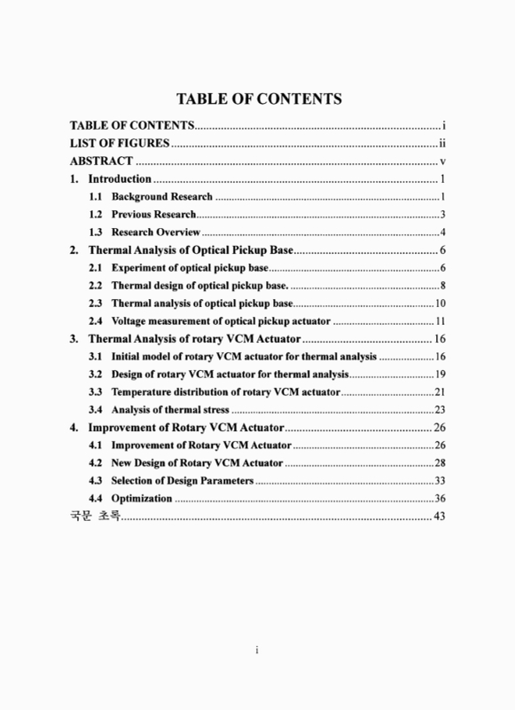
Contents
ABSTRACT 9
1. Introduction 11
1.1. Background Research 11
1.2. Previous Research 13
1.3. Research Overview 14
2. Thermal Analysis of Optical Pickup Base 16
2.1. Experiment of optical pickup base 16
2.2. Thermal design of optical pickup base. 18
2.3. Thermal analysis of optical pickup base 20
2.4. Voltage measurement of optical pickup actuator 21
3. Thermal Analysis of rotary VCM Actuator 26
3.1. Initial model of rotary VCM actuator for thermal analysis 26
3.2. Design of rotary VCM actuator for thermal analysis 29
3.3. Temperature distribution of rotary VCM actuator 31
3.4. Analysis of thermal stress 33
4. Improvement of Rotary VCM Actuator 36
4.1. Improvement of Rotary VCM Actuator 36
4.2. New Design of Rotary VCM Actuator 38
4.3. Selection of Design Parameters 43
4.4. Optimization 46
국문 초록 53
Fig. 1.1. Overall procedure 15
Fig. 2.1. overall structure of optical pickup base 16
Fig. 2.2. Target points 17
Fig. 2.3. Temperature distribution of optical pickup base 20
Fig. 2.4. comparison of experiment and simulation 21
Fig. 2.5. Experimental setup 23
Fig. 2.6. Combo drive on (317.6mW in RMS) 24
Fig. 2.7. CD write (320.4mW in RMS) 24
Fig. 2.8. Drive speed test (317.4mW in RMS) 25
Fig. 2.9. Image reading (564.4mW in RMS) 25
Fig. 3.1. Overall structure of rotary VCM actuator 27
Fig. 3.2. Flexible mode frequency (a) focusing mode (b) 2nd bending mode (c) 1st torsion mode 28
Fig. 3.3. Temperature distribution (a) pickup (72℃) (b) pickup and coil (75℃) 32
Fig. 3.4. effect of ambient temperature 33
Fig. 3.5. effect of convection coefficient 33
Fig. 3.6. Thermal stress distribution 35
Fig. 3.7. Displacement caused thermal stress 35
Fig. 4.1. Fin design 37
Fig. 4.2. Example model 39
Fig. 4.3. Design parameters 40
Fig. 4.4. Improved model 41
Fig. 4.5. Temperature distribution (a) initial model (b) improved model 42
Fig. 4.6. Candidates of design parameters (a)actuator (b)extended fin 43
Fig. 4.7. The main effect 45
Fig. 4.8. The pareto chart 45
Fig. 4.9. The two factor interaction 46
Fig. 4.10. Optimization procedure 47
Fig. 4.11. Temperature distribution (68.4℃) 48
Fig. 4.12. Flexible mode frequency (a) Focusing mode freq. (65Hz) (b) 2nd bending mode freq. (6.3kHz) (c) 1st torsion mode freq.(7.5kHz) 49
*표시는 필수 입력사항입니다.
| *전화번호 | ※ '-' 없이 휴대폰번호를 입력하세요 |
|---|
| 기사명 | 저자명 | 페이지 | 원문 | 기사목차 |
|---|
| 번호 | 발행일자 | 권호명 | 제본정보 | 자료실 | 원문 | 신청 페이지 |
|---|
도서위치안내: / 서가번호:

우편복사 목록담기를 완료하였습니다.
*표시는 필수 입력사항입니다.
저장 되었습니다.
