
 대표어
대표어


권호기사보기
| 기사명 | 저자명 | 페이지 | 원문 | 기사목차 |
|---|
결과 내 검색
동의어 포함
Title Page
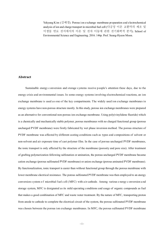
Abstract
Contents
I. INTRODUCTION 13
1.1. Introduction 13
1.2. Objective of the research 14
1.3. Structure of the research 15
II. LITERATURE REVIEW 17
2.1. Porous ion exchange membrane 17
2.2. Preparation of porous ion exchange membrane 17
2.2.1. Pre-functionalization 18
2.2.2. Post-functionalization 19
2.3. Practical and possible applications of porous IEMs 25
2.3.1. Proton exchange membrane fuel cell 27
2.3.2. Direct methanol fuel cell 29
2.3.3. Microbial fuel cell 31
2.3.4. Redox flow battery 33
III. VERIFICATION OF ION TRANSPORT THROUGH THE POROUS UNCHARGED POLY(VINYLIDENE FLUORIDE) MEMBRANES 39
3.1. Introduction 39
3.2. Experimental 41
3.2.1. Materials 41
3.2.2. Porous PVDF Membrane preparation 41
3.2.3. Membrane characterization 41
3.3. Results and discussion 46
3.3.1. Physical structure and properties of porous PVDF membranes 46
3.3.2. Membrane electrical resistance of porous PVDF membranes 56
3.3.3. Relation between physical structure of the membranes and ion conductivity 57
3.4. Conclusion 58
IV. VERIFICATION OF ION TRANSPORT THROUGH THE POROUS CHARGED POLY(VINYLIDENE FLUORIDE) MEMBRANES 61
4.1. Introduction 61
4.2. Experimental 62
4.2.1. Materials 62
4.2.2. Preparation of porous uncharged PVDF membrane 62
4.2.3. Preparation and optimization of porous sulfonated PVDF membrane 62
4.2.4. Preparation of porous aminated PVDF membrane 64
4.2.5. Membrane characterization 65
4.3. Results and discussion 66
4.3.1. Optimization of porous sulfonated PVDF membrane and preparation of porous aminated PVDF membrane 66
4.3.2. Functionality effect on ion transport and selectivity 70
4.3.3. The chemical and physical properties of the prepared porous membranes 74
4.4. Conclusion 75
V. THE POROUS CATION EXCHANGE MEMBRANE IN MICROBIAL FUEL CELL AND ITS ELECTROCHEMICAL PROPERTIES 77
5.1. Introduction 77
5.2. Experimental 79
5.2.1. Materials 79
5.2.2. Membrane preparation 80
5.2.3. Membrane characterization 80
5.2.4. MFC operation 82
5.2.5. EIS analysis of MFC 83
5.3. Results and discussion 84
5.3.1. Membrane properties 84
5.3.2. MFC Operation 88
5.3.3. EIS study for MFC 91
5.4. Conclusion 95
VI. EVALUATION OF MICROBIAL FUEL CELL PERFORMANCE WITH VARIOUS ANODE MATERIALS AND CHARGE TRANSFER BEHAVIOR IN BIOFILM 97
6.1. Introduction 97
6.2. Experimental 99
6.2.1. Materials 99
6.2.2. Membrane preparation 100
6.2.3. Membrane characterization 101
6.2.4. MFCs operation with different anode type 101
6.2.5. MFCs operation with different anode capacity 102
6.2.6. EIS study for MFC 102
6.3. Results and discussion 102
6.3.1. Membrane properties 102
6.3.2. Properties of anode materials 104
6.3.3. Performance and EIS study of MFCs with different types of anode materials 106
6.3.4. Performance and EIS study of MFCs with carbon clothes on biofilm dilatation 110
6.3.5. Performance and EIS study of MFCs with different anode capacity 115
6.4. Conclusion 122
VII. SUMMARY AND FURTHER STUDIES 123
APPENDIX) ELECTROCHEMICAL ANALYSIS ON THE PERFORMANCE OF MICROBIAL FUEL CELLS CONNECTED IN SERIES OR PARALLEL 127
A.1. Introduction 127
A.2. Experimental 128
A.2.1. Materials 128
A.2.2. MFC preparation 129
A.2.3. Performance and EIS analysis of MFCs 130
A.3. Results and discussion 130
A.3.1. Performance of MFCs 130
A.3.2. EIS study of MFC 133
A.4. Conclusion 135
국문요약 137
References 141
Curriculum Vitae 151
Figure 1.1. The structure of this study. 16
Figure 2.1. The preparation methods of cation exchange membranes 18
Figure 2.2. The chemicals used for functionalization and the steps of functionalization of previous... 22
Figure 3.1. A schematic design of the experimental set-up for the air permeability measurements. 43
Figure 3.2. Two transport mechanisms of gas molecules through a membrane pore. 43
Figure 3.3. Schematic figure of clip cell apparatus which is connected to Autolab instrument for MER... 45
Figure 3.4. Schematic diagram of transport number measurement set-up. 46
Figure 3.5. The surface and cross-section images of porous PVDF membranes prepared without any... 48
Figure 3.6. The surface and cross-section images of porous PVDF membranes prepared using DMAc as... 49
Figure 3.7. The surface and cross-section images of porous PVDF membranes prepared using DMF as... 50
Figure 3.8. The surface and cross-section images of porous PVDF membranes prepared using NMP as... 51
Figure 3.9. The cross-section images of porous PVDF membranes prepared with various non-solvent... 52
Figure 3.10. The relationship between the pore size and resistivity of the porous PVDF membranes. 57
Figure 3.11. Summary on the effect of membrane structure development by non-solvent additives. 58
Figure 4.1. Schematic diagram of sulfonation process of porous PVDF membrane. 63
Figure 4.2. Schematic flow of IEC measurement of a cation exchange membrane. 66
Figure 4.3. IEC values obtained from the membranes prepared at each sulfonation conditions. 67
Figure 4.4. The optimized sulfonation process of the porous uncharged PVDF membrane. 68
Figure 4.5. The optimized amination process of the porous uncharged PVDF membrane. 69
Figure 4.6. The schematic chemical reaction of polymer grafting on PVDF membrane and sulfonation... 69
Figure 4.7. Transport number of porous uncharged PVDF (uPVDF), porous sulfonated PVDF (sPVDF)... 73
Figure 4.8. The conductivity of porous uncharged PVDF (uPVDF), porous sulfonated PVDF (sPVDF)... 74
Figure 4.9. The FT-IR spectra of the porous uncharged, porous sulfonated and porous aminated PVDF... 75
Figure 5.1. A schematic diagram of a typical MFC configuration. 78
Figure 5.2. Schematic drawing of oxygen permeability experiment apparatus. 82
Figure 5.3. A schematic diagram of the air-cathode MFC configuration used in the study. 82
Figure 5.4. The FT-IR spectra of Nafion and the porous uncharged and sulfonated PVDF membranes. 84
Figure 5.5. The surface and cross-sectional images of the membranes 85
Figure 5.6. The polarization (solid black line) and power density (dotted blue line) curves of the MFCs... 91
Figure 5.7. (a) The EC of the electrical double layer on the electrode surface,... 92
Figure 5.8. The configuration of the air-cathode MFC used in this study and the transport mechanisms... 93
Figure 5.9. The impedance spectra of the Nafion and uncharged and porous sulfonated PVDF... 94
Figure 6.1. The schematic illustrations of (a) direct electron transfer, (b) extracellular electron transfer,... 98
Figure 6.2. Schematic flow diagram of porous PVDF membrane sulfonation with mild condition. 101
Figure 6.3. The FT-IR spectra of the porous uncharged and sulfonated PVDF membranes. 103
Figure 6.4. SEM images of porous uncharged PVDF membrane (a) and porous sulfonated PVDF... 104
Figure 6.5. The results of contact angle measurement of (a) pGF, (b) aGF, and (c) CC (A drop of water... 105
Figure 6.6. SEM images of the anode materials of (a) pGF, (b) aGF and (c) CC. 106
Figure 6.7. (a) The polarization (solid black line) and power density (dotted blue line) curves obtained... 108
Figure 6.8. (a) The impedance spectra obtained on the 35th day of continuous feeding mode operation...(이미지참조) 110
Figure 6.9. The polarization (solid black line) and power density (dotted blue line) curves of (a) the... 111
Figure 6.10. (a) The impedance spectra obtained from MFC_CC on various operation time of 13th, 35th,...(이미지참조) 113
Figure 6.11. The impedance spectra obtained from MFC_aGF on various operation time of 13th, 35th...(이미지참조) 113
Figure 6.12. The polarization resistance and capacitive component of constant phase element of second... 114
Figure 6.13. The schematic illustration of cross section of bacteria growth in the anodic chamber of... 115
Figure 6.14. The polarization (solid black line) and power density (dotted blue line) curves obtained on... 116
Figure 6.15. The impedance spectra obtained on the 35th day of continuous feeding mode operation of... 117
Figure 6.16. The polarization (solid black line) and power density (dotted blue line) curves of the MFCs... 118
Figure 6.17. The impedance spectra of the MFCs measured at different operation time 119
Figure 6.18. (a) The impedance spectra of the MFC_20CC at different applied potential on 72nd day of...(이미지참조) 121
Figure 6.19. The polarization resistance and capacitive component of constant phase element of second... 121
Figure A.1. (a) Configuration of the air-cathode MFC for this research, and the scheme of (b) series... 130
Figure A.2. The polarization (black line) and power density (blue line) curves of (a) single MFC operation,... 132
Figure A.3. The potential distribution of (a) series connected MFCs and (b) parallel connected MFCs at... 133
Figure A.4. (a) Equivalent circuit (EC) used for data regression(Kim, Shin et al. 2014)R1 is the complex... 135
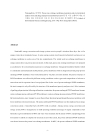
화석연료의 고갈과 환경 문제에 대한 대중의 관심이 증가함에 따라 지속가능한 에너지 전환 및 저장 장치에 대한 관심 또한 증가하였다. 수소 연료 전지, 메탄올 연료 전지, 미생물 연료 전지 등과 같은 연료 전지 시스템과 레독스 흐름 전지 등을 포함하는 2차 전지 시스템은 그 중의 하나로, 화학 에너지를 전기 에너지로 직접 변환하므로 기존의 화석 연료의 사용에 비하여 에너지 변환 효율이 매우 높다. 에너지 전환 및 저장 장치의 한 부분인 멤브레인은 시스템의 성능을 결정하는 인자 중 하나로 이온 전도성과 전자 절연성의 특징을 가져야 한다. 본 연구에서는 멤브레인의 이온 전도도를 높이고 전기 저항성을 저감시키기 위하여 다공성 이온 교환막을 제조하고, 이를 미생물 연료 전지에 적용하여 그 성능을 확인하고자 한다.
제 2장에서는 다공성 이온 교환막에 대한 기존 연구에 대한 조사를 수행하였다. 다공성 이온 교환막의 제조 방법과 적용가능한 시스템(수소 연료 전지, 미생물 연료 전지, 수계 및 비수계 레독스 흐름 전지 등)에 대하여 소개하였다.
제 3장에서는 다양한 조건 하에서 습식 상전이법을 통하여 다공성막을 제조하고, 제조된 막에 대한 이온의 이동을 확인하였다. 다양한 종류의 유기 용매(DMAc, DMF and NMP)와 비용매성 첨가제(methanol, 1-butanol and 1-octanol)를 이용하여 고분자 용액을 제조하고, 공기 노출 시간의 유무에 따라 제조된 막의 다공성 구조의 차이 및 이에 따른 이온의 이동에 대하여 관찰하였다. 제조된 막은 모두 미세 공극을 가지는 얇은 표면층과 손가락 형태의 공극 구조를 가지는 층, 스폰지 구조나 노듈 형태를 가지며 막의 하부를 지탱하는 지지층의 3층 구조를 가진다. 첨가제의 탄소 수가 증가할수록 제조된 막의 다공성은 감소하였는데, 이는 SEM 사진에서 막의 두번째 층과 지지층의 고분자 밀도가 첨가제의 탄소 수 증가와 함께 증가함을 통해서도 알 수 있다. 다공성막의 공극 크기는 뚜렷한 경향을 보이지는 않았으나, 고분자, 유기용매, 첨가제의 관계에 복잡하게 영향을 받는 것으로 보인다. 막에 대한 이온의 전도도는 첨가제가 사용되었을 때 더욱 활발하였으며, 특히 1-butanol이 첨가된 다공성막이 대체적으로 높은 이온 전도도를 보였다. 제조된 막의 공극 크기와 이온 전도도 결과를 바탕으로 이후의 연구에 가장 적합한 다공성막을 선정하였는데, 이는 PVDF를 고분자로 하고, DMF를 유기 용매로 하며, 20 wt%의 1-butanol이 첨가된 용액으로 공기 노출 시간 없이 제조된 다공성막이다.
제 4장에서는 3장에서 선정된 다공성막을 이용하여 다공성 양이온 교환막 또는 다공성 음이온 교환막을 제조하고, 다공성 이온 교환막에 대한 이온의 이동에 대한 관찰을 수행하였다. 먼저, sulfonation 조건을 다양하게 적용하여 다공성막의 이온 교환막으로의 처리 조건을 최적화하였다. 최적화된 grafting 중합 반응과 sulfonation 또는 amination 조건을 이용하여 다공성 양이온 교환막과 다공성 음이온 교환막이 성공적으로 제조되었으며, 이를 막의 이온 교환 능력과 FT-IR을 통하여 증명할 수 있었다. 막에 대한 이온의 이동 현상은 이동수와 전기 저항을 통하여 관찰하였다. 이온 교환기를 가지고 있지 않은 다공성막의 경우에는 수계에 존재하는 이온의 종류에 따라 선택성이 달라진다. Sulfonation 처리를 통해 만들어진 다공성 양이온 교환막은 다공성막에 비하여 높은 양이온 선택성을 보이며, amination 처리를 통해 만들어진 다공성 음이온 교환막은 다공성막보다 높은 음이온 선택성을 보인다. 또한, 막의 전도도도 sulfonation 또는 amination 처리 후에 증가함을 관찰할 수 있었다. 이는 제조된 다공성 이온 교환막이 다공성 구조에도 불구하고 이온을 선택적으로 투과할 수 있다는 것과 막에 존재하는 기능기가 이온의 이동을 향상시킨다는 것을 의미한다.
제 5장에서는 4장에서 제조된 다공성 양이온 교환막을 에너지 전환 시스템의 하나인 미생물 연료 전지(MFC)에 적용하여, 막을 통한 이온 이동의 향상이 시스템의 성능에 어떠한 영향을 미치는 지에 대하여 살펴보았다. 성능 비교를 위한 대조군으로는 연료 전지에 가장 널리 사용되고 있는 비다공성 이온 교환막인 나피온막과 3장에서 선정된 PVDF 다공성막이 사용되었다. 3종류의 막 중에 다공성 양이온 교환막이 가장 높은 전력 밀도를 보였는데, 이는 다공성 양이온 교환막의 높은 이온 교환 능력과 낮은 전기 저항성, 높은 양이온 선택성에서 기인했음을 알 수 있다. 제조된 막 내부의 다공성 표면에 존재하는 이온교환기로 인하여 막의 친수성이 증가하고, 이온 채널이 팽창함으로써 이온의 이동이 나피온막과 다공성막보다 가속화된 것으로 여겨진다. 또한, MFC의 전기화학 임피던스 분석을 통하여 시스템 계면에 존재하는 전기 저항 값이 다른 막이 적용된 MFC보다 낮음을 알 수 있었다.
제 6장에서는 MFC의 산화 전극의 특성에 따른 시스템의 성능과 전기화학적 특징을 분석하였다. MFC의 산화 전극은 미생물을 촉매로 이용하여 유기물을 분해, 수소 이온과 전자를 생산하는 작용이 이루어지는 곳으로 시스템의 성능을 결정하는 또 하나의 중요한 인자이다. 소수성인 graphite felt(pGF), 친수성인 graphite felt(aGF), 친수성인 carbon cloth(CC)의 전극 물질이 사용되었다. 세 종류의 전극 물질 중 CC를 포함하는 MFC가 가장 높은 성능을 보였는데, 이는 CC의 높은 비표면적으로 인한 것으로 여겨진다. 임피던스 분석을 통하여 서로 다른 산화 전극이 MFC의 전기화학적 계면 특징에 미치는 영향을 알 수 있었다. 친수성 전극인 aGF와 CC의 경우에는 낮은 복합 저항값과 작은 첫 번째 semi-circle을 얻은데 반하여, 소수성 전극인 pGF는 상대적으로 높은 복합 저항값과 큰 첫 번째 semi-circle을 보였다. 이는 산화극과 환원극 사이에 막이 존재하며 두 전극과 직접적으로 접촉하는 구조로 되어있기 때문에 멤브레인 계면을 대표하는 첫 번째 semi-circle의 크기에도 전극의 특성이 영향을 끼치기 때문이다. 또한, 전극의 계면을 나타내는 두 번째 semi-circle의 경우, pGF와 aGF와 비교하여 상대적으로 큰 값이 CC에서 관찰되었다. 이를 평가하기 위하여 시간에 따른 MFC의 성능과 임피던스 분석을 수행하였고, 운전 시간이 증가할수록 MFC의 성능의 증가와 전극의 분극 저항의 감소를 관찰할 수 있었다. 이는 운전 시간이 증가함에 따라 형성되는 미생물 층의 증가가 전극의 분극 저항을 감소시키며 더 높은 전력을 발생할 수 있도록 한다는 결론과 같은 의미이며, MFC의 미생물 층이 전자 전도도를 가짐을 알 수 있다. 이를 다시 한 번 확인하기 위하여, 전압에 따른 임피던스 측정을 시도하였고, 높은 전류를 생산할수록(전기 활성 미생물이 많아 질수록 또는 미생물의 활성도가 높아질수록) 낮은 분극 저항을 보임을 알 수 있었다.*표시는 필수 입력사항입니다.
| 전화번호 |
|---|
| 기사명 | 저자명 | 페이지 | 원문 | 기사목차 |
|---|
| 번호 | 발행일자 | 권호명 | 제본정보 | 자료실 | 원문 | 신청 페이지 |
|---|
도서위치안내: / 서가번호:

우편복사 목록담기를 완료하였습니다.
*표시는 필수 입력사항입니다.
저장 되었습니다.
