

권호기사보기
| 기사명 | 저자명 | 페이지 | 원문 | 기사목차 |
|---|
| 대표형(전거형, Authority) | 생물정보 | 이형(異形, Variant) | 소속 | 직위 | 직업 | 활동분야 | 주기 | 서지 | |
|---|---|---|---|---|---|---|---|---|---|
| 연구/단체명을 입력해주세요. | |||||||||
|
|
|
|
|
|
* 주제를 선택하시면 검색 상세로 이동합니다.
표제지
서지정보양식
제출문
요약문
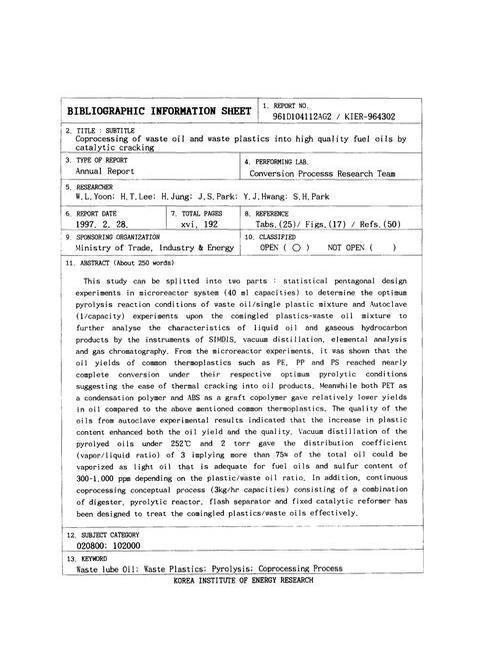
Abstract
표목차
그림목차
목차
제1장 서론 21
제1절 연구의 필요성 21
제2절 연구범위 23
제2장 문헌조사 24
제1절 열분해 반응기구 24
제2절 촉매분해반응 26
1. 산촉매 26
2. 염기성촉매 34
3. 최근 연구동향 36
제3절 선진각국의 최근 공정개발 연구동향 40
제4절 국내의 폐윤활유 및 폐플라스틱 처리실태 80
제3장 동시분해반응실험 89
제1절 시료 89
1. 플라스틱 시료 89
2. 폐윤활유 시료 89
제2절 회분식 반응기 열분해실험[내용누락;p.72] 92
1. 실험계획 (experimental design) 41-45) 93
가. 서론 93
나. 반응표면 실험계획(response surface experimental design) 94
2. 미분반응기 열분해 실험 98
3. Autoclave 열분해반응 실험 101
4. 분석 104
가. 오일성분의 압력여과 분석 104
나. 탄화수소기체분석 106
다. 오일분석 111
1) SIMDIS 111
2) 진공증류 111
3) 원소 및 발열량 분석 116
제3절/제4절 실험결과 및 고찰 117
1. 미분반응기 열분해반응실험 117
가. 각 플라스틱의 열분해 특성 117
나. 각 플라스틱의 최적 열분해 반응조건 122
2. Autoclave 열분해반응 127
가. 탄화수소기체 분석 127
나. 오일성분 분석 133
다. 진공증류 133
라. 원소 및 발열량 분석 138
제4장 연속식 동시처리 개념공정 기본설계 141
제1절 연속식 시험공정 설계개요 141
1. 설계기준 141
가. 처리용량 141
나. 공정변수 141
2. 각 단위공정의 개요 142
가. 소화조 (Digester) 144
나. 열분해 반응기 (Pyrolysis reactor) 144
다. 평형 플래쉬 드럼 (Euqilibrium flash drum) 144
라. 고정촉매층반응기 (Catalytic fixed bed) 145
마. 열교환기 (Condenser) 145
바. 기/액-분리기 (Gas/liquid-separator) 145
제2절 연속식 시험공정 가동 및 운전정지 지침 145
1. start-up 및 정상운전 145
2. 운전정지 146
제5장 결론 148
참고문헌 153
부록 158
위탁연구보고서 : 폐프라스틱과 폐유의 기초분해 반응 특성 연구 159
제출문 161
요약문 163
목차 165
제1장 서론 169
제2장 점도 계산 171
제3장 실험장치 및 방법 174
제1절 실험장치 174
제2절 실험방법 174
제4장 결과 및 고찰 176
제1절 폐윤활유와 LDPE 혼합물의 점도특성 176
제2절 폐윤활유와 HDPE 혼합물의 점도특성 182
제3절 폐윤활유와 PP 혼합물의 점도특성 186
제4절 LDPE와 HDPE 혼합물의 혼합비변화에 따른 점도특성 190
제5절 LDPE와 PP 혼합물의 혼합비변화에 따른 점도특성 194
제6절 LDPE와 PET 혼합물의 혼합비변화에 따른 점도특성 199
제7절 패윤활유와 혼합한 프라스틱종류에 따른 점도특성 202
제5장 결론 210
사용기호 211
참고문헌 212
촉매분해를 이용한 폐유-폐플라스틱의 고급연료유화 기술연구 18
[Figure 1] Plastics are recycled into liquid petroleum, carbon, and noncondensable gases in the proprietary Conard(Conrad) recycling process. 58
[Figure 2] Gas chromatogram of liquid product. 62
[Figure 3] Product yields from Conard parmetric study. 65
[Figure 4] Carbon number distribution of the waste lube-oil feed and pyrolysed oil in an Autoclave reactor. 91
[Figure 5] Experimental apparatus. 99
[Figure 6] Typical time-temperature-system pressure profile. 103
[Figure 7] Procedure of pressure filtration. 105
[Figure 8] Retention time distribution of standard gas. 108
[Figure 9] Retention time distribution of hydrocarbons in gamma alumina column. 110
[Figure 10] Vacuum distillation unit. 113
[Figure 11] Oil yield contour of HDPE with the ratio of plastic to waste oil. 124
[Figure 12] Results of simultaneous thermal cracking of waste oil and mixed plastic in a autoclave. (460℃, 30min) 128
[Figure 13] Retention time distribution of hydrocarbons. 129
[Figure 14] Carbon number distribution of gas phase. 131
[Figure 15] The effect of plastic contents on the oil yield of gasoline, kerosen, and light oil grade. 134
[Figure 16] Carbon number distribution. A :Pyrolysed oil(plastic content of 66wt%) B : top products of vacuum distillation of A 137
[Figure 17] Schematic diagram of the continuous process 143
폐프라스틱과 폐유의 기초분해 반응 특성 연구 166
Figure 1. A schematic(shematic) diagram of experimental apparatus 175
Figure 2. The effect of shear rate of the waste lubricating oil/LDPE mixture on viscosity (LDPE : Waste lubricating oil = 1:1 wt%) 179
Figure 3. The effect of shear rate of the waste lubricating oil/LDPE mixture on viscosity (LDPE : Waste lubricating oil = 1:1.5 wt%) 180
Figure 4. The effect of shear rate of the waste lubricating oil/LDPE mixture on viscosity (LDPE : Waste lubricating oil = 1:2 wt%) 181
Figure 5. The effect of shear rate of the waste lubricating oil/HDPE mixture on viscosity (HDPE : Waste lubricating oil = 1:1 wt%) 183
Figure 6. The effect of shear rate of the waste lubricating oil/HDPE mixture on viscosity (HDPE : Waste lubricating oil = 1:1.5 wt%) 184
Figure 7. The effect of shear rate of the waste lubricating oil/HDPE mixture on viscosity (HDPE : Waste lubricating oil = 1:2 wt%) 185
Figure 8. The effect of shear rate of the waste lubricating oil/PP mixture on viscosity (PP : Waste lubricating oil = 1:1 wt%) 187
Figure 9. The effect of shear rate of the waste lubricating oil/PP mixture on viscosity (PP : Waste lubricating oil = 1:1.5 wt%) 188
Figure 10. The effect of shear rate of the waste lubricating oil/PP mixture on viscosity (PP : Waste lubricating oil = 1:2 wt%) 189
Figure 11. The effect of shear rate of the mixture of LDPE/HDPE and waste lubricating oil on viscosity (LDPE/HDPE : Waste lubricating oil = 1:1 wt%) 191
Figure 12. The effect of shear rate of the mixture of LDPE/HDPE and waste lubricating oil on viscosity (LDPE/HDPE : Waste lubricating oil = 1:1.5 wt%) 192
Figure 13. The effect of shear rate of the mixture of LDPE/HDPE and waste lubricating oil on viscosity (LDPE/HDPE : Waste lubricating oil = 1:2 wt%) 193
Figure 14. The effect of shear rate of the mixture of LDPE/PP and waste lubricating oil on viscosity (LDPE/PP : Waste lubricating oil = 1:1 wt%) 196
Figure 15. The effect of shear rate of the mixture of LDPE/PP and waste lubricating oil on viscosity (LDPE/PP : Waste lubricating oil = 1:1.5 wt%) 197
Figure 16. The effect of shear rate of the mixture of LDPE/PP and waste lubricating oil on viscosity (LDPE/PP : Waste lubricating oil = 1:2 wt%) 198
Figure 17. The effect of shear rate of the mixture of LDPE/PET and waste lubricating oil on viscosity (LDPE/PET : Waste lubricating oil = 1:1 wt%) 200
Figure 18. The effect of shear rate of the mixture of LDPE/PET and waste lubricating oil on viscosity (LDPE/PET : Waste lubricating oil = 1:1.5 wt%) 201
Figure 19. The effect of shear rate of the mixture of polymer and waste lubricating oil on viscosity (Polymer mixture : Waste lubricating oil = 1:1 wt%, 280℃) 204
Figure 20. The effect of shear rate of the mixture of polymer and waste lubricating oil on viscosity (Polymer mixture : Waste lubricating oil = 1:1 wt%, 300℃) 205
Figure 21. The effect of shear rate of the mixture of polymer and waste lubricating oil on viscosity (Polymer mixture : Waste lubricating oil = 1:1.5 wt%, 280℃) 206
Figure 22. The effect of shear rate of the mixture of polymer and waste lubricating oil on viscosity (Polymer mixture : Waste lubricating oil = 1:1.5 wt%, 300℃) 207
Figure 23. The effect of shear rate of the mixture of polymer and waste lubricating oil on viscosity (Polymer mixture : Waste lubricating oil = 1:2 wt%, 280℃) 208
Figure 24. The effect of shear rate of the mixture of polymer and waste lubricating oil on viscosity (Polymer mixture : Waste lubricating oil = 1:2 wt%, 300℃) 209
| 등록번호 | 청구기호 | 권별정보 | 자료실 | 이용여부 |
|---|---|---|---|---|
| 0000715309 | 665.5384 ㅌ363ㅊ | v.1 | 서울관 서고(열람신청 후 1층 대출대) | 이용가능 |
| 0000715310 | 665.5384 ㅌ363ㅊ | v.1 | 서울관 서고(열람신청 후 1층 대출대) | 이용가능 |
*표시는 필수 입력사항입니다.
| 전화번호 |
|---|
| 기사명 | 저자명 | 페이지 | 원문 | 기사목차 |
|---|
| 번호 | 발행일자 | 권호명 | 제본정보 | 자료실 | 원문 | 신청 페이지 |
|---|
도서위치안내: / 서가번호:

우편복사 목록담기를 완료하였습니다.
*표시는 필수 입력사항입니다.
저장 되었습니다.
