
 대표어
대표어

권호기사보기
| 기사명 | 저자명 | 페이지 | 원문 | 기사목차 |
|---|
결과 내 검색
동의어 포함
표제지
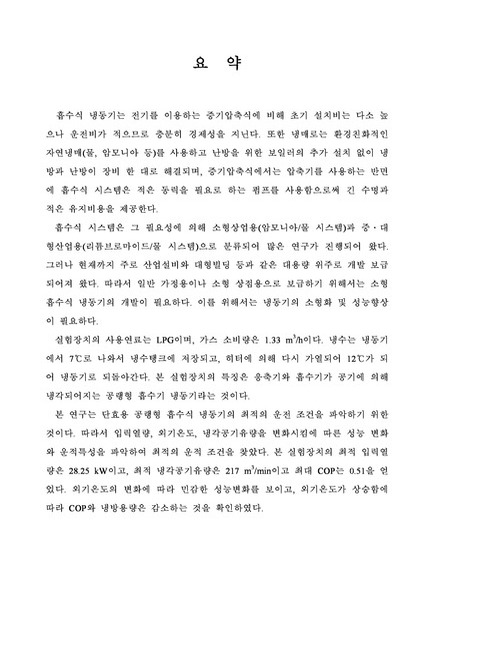
요 약
목차
Nomenclature 7
제 1 장 서 론 12
제 2 장 흡수식 시스템 14
2.1 흡수식 시스템의 개요 14
2.2 물/리튬브로마이드(H₂O/LiBr) 흡수식 시스템 20
2.2.1 리튬브로마이드(LiBr) 20
2.2.2 물(H₂O) 20
2.2.3 물-리튬브로마이드(H₂O/LiBr) 사이클 23
2.3 암모니아-물(NH₃/H₂O) 흡수식 시스템 24
2.3.1 암모니아(NH₃) 24
2.3.2 암모니아(NH₃) 농도측정법 26
2.3.3 암모니아-물(NH₃/H2O) 흡수식 사이클 27
2.3.4 GAX(Generator Absorber heateXchange) 사이클 30
2.3.5 GAX 사이클의 응용 31
제 3 장 실 험 36
3.1 실험장치 36
3.1.1 버너와 가스 입력 조절장치 41
3.1.2 증발기(Evaporator) 45
3.1.3 제어 및 안전장치 46
3.1.4 계측기 및 제어장치 47
3.2 실험방법 54
3.3 데이터 처리 및 오차해석 56
3.3.1 성적계수(COP) 56
3.3.2 버너효율 58
제 4 장 결과 및 토론 61
4.1 입력열량 변화에 따른 성능분석 61
4.2 외기온도 변화에 따른 성능분석 65
4.3 냉각공기유량 변화에 따른 성능분석 67
제 5 장 결 론 71
참고문헌 72
Abstract 79
감사의 글 80
Fig. 1 Schematic diagram of H₂O/LiBr Cycle 23
Fig. 2 Schematic diagram of NH₃-H₂O cycle 27
Fig. 3 Standard GAX cycle 30
Fig. 4 HGAX Type A 33
Fig. 5 HGAX Type B 33
Fig. 6 HGAX Type C 34
Fig. 7 HGAX Type D 34
Fig. 8 PGAX and LGAX 35
Fig. 9 Diagram of 5RT single-effect NH3/H₂O absorption chiller(Servel, US) 39
Fig. 10 Burner and Gas control unit 43
Fig. 11 Gas pressure gage 43
Fig. 12 Inlet Gas pressure tap 43
Fig. 14 Auto gas safety unit 44
Fig. 15 Low gas pressure control unit 44
Fig. 16 High gas pressure control unit 44
Fig. 17 Evaporator 45
Fig. 18 Chilled Water Tank 45
Fig. 19 Cycle diagram of the absorption chiller 48
Fig. 20 Pressure measurement 49
Fig. 21 Measurement part of pressure gage 49
Fig. 22 Indicator of pressure gage 49
Fig. 23 Location of temperature measurement using thermocouple 50
Fig. 24 Location of temperature measurement using RTD 50
Fig. 25 Pipe laying 51
Fig. 26 Magnetic flow meter 51
Fig. 27 Circulation pump 51
Fig. 28 Gas supply equipments 52
Fig. 29 Gas mass flow meter 52
Fig. 30 Gas flow meter 52
Fig. 31 Experimental equipment 53
Fig. 32 Constant temperature room 53
Fig. 33 Boiler 53
Fig. 34 Fan unit 53
Fig. 35 Schematic diagram of experimental equipments 55
Fig. 36 Control volume of the desorber 60
Fig. 37 Pressure versus gas input, Qinput 63
Fig. 38 Exhaust gas temperature and burner efficiency versus Qinput 63
Fig. 39 COP and cooling capacity versus Tg 64
Fig. 40 COP and burner efficiency versus exhaust gas 64
Fig. 41 COP and cooling capacity versus Tambient 66
Fig. 42 Pressure versus Tambient 66
Fig. 43 COP and cooling capacity versus air flux 69
Fig. 44 △Tunits versus air flux 69
Fig. 45 Pressure versus air flux 70
*표시는 필수 입력사항입니다.
| 전화번호 |
|---|
| 기사명 | 저자명 | 페이지 | 원문 | 기사목차 |
|---|
| 번호 | 발행일자 | 권호명 | 제본정보 | 자료실 | 원문 | 신청 페이지 |
|---|
도서위치안내: / 서가번호:

우편복사 목록담기를 완료하였습니다.
*표시는 필수 입력사항입니다.
저장 되었습니다.
