
 대표어
대표어
권호기사보기
| 기사명 | 저자명 | 페이지 | 원문 | 기사목차 |
|---|
결과 내 검색
동의어 포함
Title Page
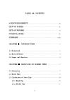
Contents
NOMENCLATURE 14
SUMMARY 18
CHAPTER I. INTRODUCTION 20
1.1. Background 20
1.2. Research History 22
1.3. Objective and Scope 24
CHAPTER II. BEHAVIOR OF BURIED PIPES 26
2.1. Introduction 26
2.2. Buried pipes 27
2.3. Classification of Sewer Pipe 29
2.3.1. Rigid Pipe 34
2.3.2. Flexible Pipe 36
2.4. Soil-Pipe Interaction 37
2.4.1. Marston Load Theory 37
2.4.2. Ring Deflection 40
CHAPTER III. DESIGN AND INSTALLATION OF BURIED PIPE 46
3.1. External Load Distribution on the Buried Pipes 46
3.1.1. Prism Load 46
3.1.2. Live Load 47
3.1.3. Analysis of Load Effect 53
3.2. Design of Buried Rigid Pipe 55
3.3. Design of Buried Flexible Pipe 57
3.3.1. Pipe Performance Limits 61
3.3.2. Deflection 62
3.3.3. Strain Limit 67
3.3.4. Buckling 68
3.4. Installation of Buried Flexible Pipe 70
3.5. Flexible Pipe Installation Theory 71
3.6. Terminology of Pipe Embedment Materials 73
3.7. Compaction of Soil 76
3.7.1. Compaction of Class I and II Materials 80
3.7.2. Compaction of Class III and IV Materials 82
3.7.3. Density Checks 82
3.7.4. Trench Construction 83
3.7.5. Trench Width 84
3.7.6. Trench Length 85
3.7.7. Stability of the Trench 86
3.7.8. Stability of Trench Floor 88
3.7.9. Stability of Trench Walls 90
CHAPTER IV. MECHANICAL PROPERTIES OF FLEXIBLE PIPES 92
4.1. Tensile Strength Test 92
4.1.1. Specimen Preparation for the Tensile Strength Test 92
4.1.2. Tensile Strength Test Results 95
4.2. Ring Stiffness of Flexible Pipes 103
4.2.1. Classical Theory of Ring Stiffness 103
4.2.2. Parallel Plate Loading Test 112
4.2.3. Prediction of Pipe Stiffness by Analytical Study 120
CHAPTER V. Field Test of Flexible Pipes 127
5.1. Objective 127
5.2. Method and Overview of Field Test 128
5.3. Deflection Measurement and Discussion 134
CHAPTER VI. INVESTIGATION ON THE RING DEFLECTION LIMITATIONOF BURIED FLEXIBLE PIPE 151
6.1. Theoretical Study 151
6.2. Analytical Study 160
6.2.1. Analysis Condition and Assumption 161
6.2.2. Result of the Finite Element Analysis 164
CHAPTER VII. CONCLUSION 169
BIBLIOGRAPHY 172
VITA 181
국문요약 182
Fig. 1.1. Nomenclature of Cross Section of Buried Pipes (Watkins, 2000) 25
Fig. 2.1. Load Transfer Mechanism of Flexible Pipe (Moser, 2001) 36
Fig. 2.2. Force Diagram for a Conduit in a Ditch (Suleiman, 2002) 38
Fig. 2.3. Infinite Medium with an Imaginary Circle (Watkins, 2000) 42
Fig. 2.4. Ratio of Areas 44
Fig. 3.1. Load Distribution of Live Load 51
Fig. 3.2. Vertical Pressure due to Overburden 54
Fig. 3.3. Assumed Soil Stress Distribution on Flexible Pipe (Suleiman, 2002) 58
Fig. 3.4. Flexible Pipe Deflection and Elongation (Watkins, 2000) 63
Fig. 3.5. Stages of Metal Flexible Pipes Deflection (Spangler, 1941) 65
Fig. 3.6. Types of Deformations in PVC Flexible Pipes (Rogers et al., 1941) 66
Fig. 3.7. Pipe Trench (Plastic Pipe Institute, 2007) 73
Fig. 4.1. Tensile Strength Test Specimen 94
Fig. 4.2. Tensile Strength Test Set-up 96
Fig. 4.3. Failure Mode of Test Specimen 98
Fig. 4.4. Stress-Strain Relationship of the PE 100
Fig. 4.5. Stress-Strain Relationship of the PVC 101
Fig. 4.6. Stress-Strain Relationship of the GFRP 102
Fig. 4.7. Bending of a Thin Curved Bar (Timoshenko, 1961) 103
Fig. 4.8. Ring of Radius Compressed by Two Forces Action (Timoshenko,1961) 107
Fig. 4.9. Parallel Plate Loading Test Condition 113
Fig. 4.10. Parallel Plate Loading Test Specimen 115
Fig. 4.11. Parallel Plate Loading Test Set-up 117
Fig. 4.12. Load-Ring Deflection Relationship 119
Fig. 4.13. AutoCad Modeling of Flexible Pipe 122
Fig. 4.14. Finite Element Model of Flexible Pipe 123
Fig. 4.15. Finite Element Mesh of Flexible Pipe 124
Fig. 4.16. Deflected shape of Flexible Pipe 125
Fig. 5.1. Location of Field Test 129
Fig. 5.2. Installation of Flexible Pipe 131
Fig. 5.3. Compaction of Backfill Material 132
Fig. 5.4. After Installation of Flexible Pipes 133
Fig. 5.5. PE Double-Wall Pipe with 95% Standard Proctor Density 136
Fig. 5.6. PE Double-Wall Pipe with 80% Standard Proctor Density 136
Fig. 5.7. PE Multi-Wall Pipe with 95% Standard Proctor Density 139
Fig. 5.8. PE Multi-Wall Pipe with 80% Standard Proctor Density 139
Fig. 5.9. PE Seamless Pipe with 95% Standard Proctor Density 142
Fig. 5.10. PE Seamless Pipe with 80% Standard Proctor Density 142
Fig. 5.11. PVC Double-Wall Pipe with 95% Standard Proctor Density 145
Fig. 5.12. PVC Double-Wall Pipe with 80% Standard Proctor Density 145
Fig. 5.13. GFRP Pipe A-Type with 95% Standard Proctor Density 147
Fig. 5.14. GFRP Pipe A-Type with 80% Standard Proctor Density 147
Fig. 5.15. GFRP Pipe B-Type with 95% Standard Proctor Density 149
Fig. 5.16. GFRP Pipe B-Type with 80% Standard Proctor Density 149
Fig. 6.1. Buried Depth with respect to Ring Deflection Ratio 155
Fig. 6.2. SBHQ6 Element (Degree of Freedom showed at the Node 3 only) 162
Fig. 6.3. Finite Element Model of Flexible Pipe 163
Fig. 6.4. Boundary Condition of Finite Element Model 163
Fig. 6.5. Ring Deflection of Finite Element Model 164
Fig. 6.6. Comparison of Result of PE Pipe 165
Fig. 6.7. Comparison of Result of PVC Pipe 166
Fig. 6.8. Comparison of Result of GFRP Pipe 167
이 논문은 지중매설된 연성관의 관변형 조사에 대한 결과이다. 지중에 매설된 연성관의 설계방법은 국내 (하수도시설기준, 2011)과 국외 (ASTM D 2412)방법으로 크게 분류될 수 있다. 실제 현장에 매설되는 연성관의 설계 식은 ASTM D 2412에서 제시하고 있는 Iowa Formula의 방법이 타당하다는 것을 알 수 있었으며, 국내외 연성관의 시공방법을 조사한 결과 시공방법 은 거의 동일한 기준으로 제안되고 있는 것을 확인하였다.
이 연구에서는 PE, PVC, GFRP를 대상으로 연성관의 설계를 위한 관의 재료역학적 성질 조사와 구조적 거동을 조사하여 관변형을 예측할 수 있는 기초자료로 활용하였으며 유한요소해석을 사용하여 구조적 거동조사 (원강성 시험, 즉 편평시험)과 비교하여 시험을 수행하지 않아도 관의 강성을 예측할 수 있도록 하였다.
연성관의 현장매설실험은 실제 매립후 시간의 경과에 따른 관의 변형거동과 관 주변 토사의 다짐정도가 관변형에 미치는 영향을 조사하기 위해 현장매설실험을 수행하였다. 실험에서는 다짐도 80% 이하와 95% 이상의 2종류의 다짐도를 고려하였다. 현장매설실험은 PE 관의 경우 이중벽관, 다중벽관, 심레스관 3종을 대상으로 하였으며, PVC 관은 이중벽관을 대상으로 하였고 GFRP 관은 강성(SN 1000, SN 2000)에 따라 2종으로 하였다. 실험에서는 150일 동안 모든 관종의 변형거동을 측정하였다. 측정결과 PE 관종 일부에서 다짐도 80% 이하인 경우 관변형 5%를 초과하였으며, 그 의의 관종에서는 5% 이내로 측정되었다.
설계식에 의한 관종별 관변형을 예측하였고, 유한요소해석 프로그램을 사용하여 이 연구에서 시험에 의해 구한 재료의 역학적 성질과 단면치수를 적용하여 관종에 따른 관변형을 예측하고 이론식에 의한 관변형 예측결과 와 비교하였다. 그 결과 관종별로 다소 차이는 있으나 최대 차이는 10% 이내로 나타났다. 따라서, 유한요소해석을 통한 관변형 예측이나 이론식에 의한 관변형 예측 결과를 이용하여 연성관의 설계가 가능함을 확인하였다.*표시는 필수 입력사항입니다.
| 전화번호 |
|---|
| 기사명 | 저자명 | 페이지 | 원문 | 기사목차 |
|---|
| 번호 | 발행일자 | 권호명 | 제본정보 | 자료실 | 원문 | 신청 페이지 |
|---|
도서위치안내: / 서가번호:

우편복사 목록담기를 완료하였습니다.
*표시는 필수 입력사항입니다.
저장 되었습니다.
