
 대표어
대표어


권호기사보기
| 기사명 | 저자명 | 페이지 | 원문 | 기사목차 |
|---|
결과 내 검색
동의어 포함
표제지
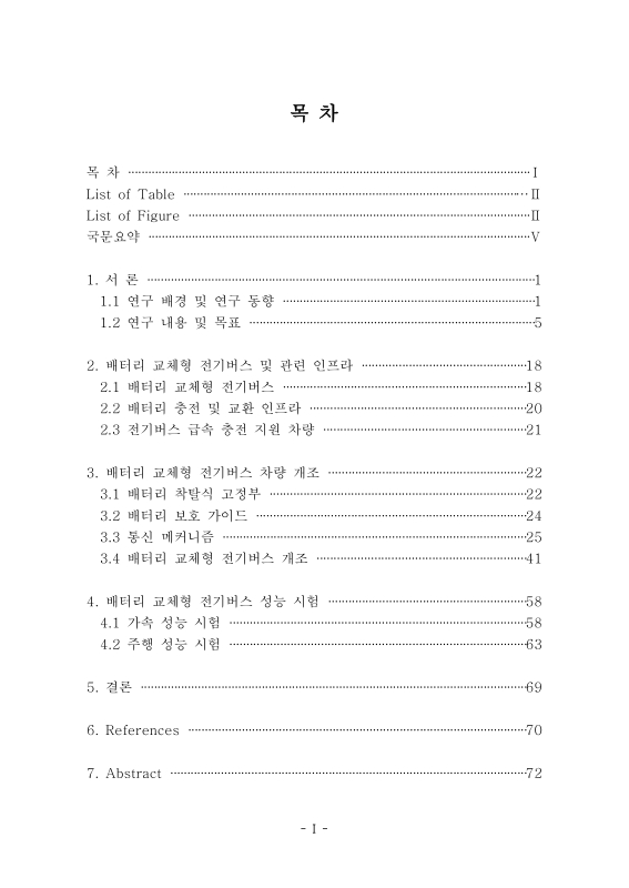
목차
국문요약 8
1. 서론 9
1.1. 연구 배경 및 연구 동향 9
1.2. 연구 내용 및 목표 13
1.2.1. 배터리 교체형 전기버스 개조 차량 개발 13
1.2.2. 배터리 교체형 전기버스의 통합 시스템 구축 22
2. 배터리 교체형 전기버스 및 관련 인프라 26
2.1. 배터리 교체형 전기버스 26
2.2. 배터리 충전 및 교환소 28
2.3. 전기버스 급속 충전 지원 차량 29
3. 배터리 교체형 전기버스 차량 개조 30
3.1. 배터리 착탈식 고정부 30
3.2. 배터리 보호 가이드 32
3.3. 통신 메커니즘 33
3.3.1. 관리 서버 관점에서의 통신 메커니즘 33
3.3.2. 차량 관점에서의 통신 메커니즘 37
3.4. 배터리 교체형 전기버스 개조 49
3.4.1. QTP 장착을 위한 보강 구조 설계 49
3.4.2. 고전압 및 저전압 배선 51
3.4.3. 전기버스 개조 차량 제작 56
4. 배터리 교체형 전기버스 성능 시험 66
4.1. 가속 성능 시험 66
4.2. 주행 성능 시험 71
5. 결론 77
6. References 78
7. Abstract 80
Fig 1.1. e-Primus electric bus 10
Fig 1.2. On-line electric bus (OLEV) 10
Fig 1.3. Need for battery commonization of electric bus 11
Fig 1.4. Battery swappable electric bus with infrastructure 12
Fig 1.5. PSAT developed by Argonne National Lab. 13
Fig 1.6. Conversion concept of electric bus 14
Fig 1.7. Graph of nuremberg urban bus driving cycle 17
Fig 1.8. Result from energy simulation (Nuremberg) 18
Fig 1.9. Graph of CBD bus driving cycle 19
Fig 1.10. Result from energy simulation (CBD) 20
Fig 1.11. Graph of manhattan urban bus driving cycle 21
Fig 1.12. Result from energy simulation (Manhattan) 22
Fig 1.13. VCU composition for driving strategy 23
Fig 1.14. Flow chart of battery swapping sequence 24
Fig 2.1. Battery swappable electric bus (Smart e-Bus) 27
Fig 2.2. Quick Changing Machine (QCM) with Smart e-Bus 28
Fig 2.3. Vehicle to support charging (Smart EB Care) 29
Fig 3.1. 3D modeling about Quick Top Pick-up (QTP) 30
Fig 3.2. Quick Top Pick-up (QTP) with battery 31
Fig 3.3. 3D modeling about Roof Door 32
Fig 3.4. Flow chart before entering the situation 34
Fig 3.5. Flow chart after entering the situation 36
Fig 3.6. Flow chart in terms of VCU (Before) 38
Fig 3.7. Flow chart in terms of Roof Door (Before) 39
Fig 3.8. Flow chart in terms of air blower (Before) 40
Fig 3.9. Flow chart in terms of connector (Before) 41
Fig 3.10. Flow chart in terms of clamp (Before) 42
Fig 3.11. Flow chart in terms of VCU (After) 44
Fig 3.12. Flow chart in terms of Roof Door (After) 45
Fig 3.13. Flow chart in terms of air blower (After) 46
Fig 3.14. Flow chart in terms of connector (After) 47
Fig 3.15. Flow chart in terms of clamp (After) 48
Fig 3.16. Isometric view about QTP mounting frame 50
Fig 3.17. Drawing about QTP mounting frame 50
Fig 3.18. Structure to reinforce QTP mounting frame 51
Fig 3.19. Low voltage wiring about swappable battery 53
Fig 3.20. Schematic diagram of high voltage and low voltage wiring 56
Fig 3.21. Task for mounting drive motor 57
Fig 3.22. Task for mounting radiator and water pump 57
Fig 3.23. Task for mounting auxiliary motor and inverter 58
Fig 3.24. Task for mounting braking resistor 58
Fig 3.25. Task for high voltage wiring 59
Fig 3.26. E-Powertrain of Smart e-Bus 59
Fig 3.27. Task for mounting QTP frame 60
Fig 3.28. Task for reinforcing QTP frame 60
Fig 3.29. Task for mounting QTP 61
Fig 3.30. Task for mounting Roof Door 61
Fig 3.31. Task for mounting fixed battery 62
Fig 3.32. Task for mounting swappable battery 63
Fig 3.33. Task for mounting display module 63
Fig 3.34. GUI for user to display in battery exchange situation 64
Fig 3.35. BTM UI in driving situation 64
Fig 3.36. BTM UI in battery exchange situation 65
Fig 3.37. Interior and exterior design of Smart e-Bus 65
Fig 4.1. According to acceleration, battery SOC variation 67
Fig 4.2. According to acceleration, limited battery output 68
Fig 4.3. Battery current and motor torque variation 69
Fig 4.4. According to the driving cycle, battery SOC variation 72
Fig 4.5. According to the driving cycle, motor torque variation 74
Fig 4.6. According to the driving cycle, motor power variation 75
현재, 지구 온난화 등의 환경문제로 세계 각국에서는 전 산업 분야에서 탄소 배출량 저감을 위한 노력이 확산되고 있다. 이러한 문제를 해결하기 위하여, 전체 탄소 배출량의 20%를 차지하는 수송 분야에서 전기자동차를 활용하고자 하는 움직임이 증대되고 있다. 이러한 전기 자동차의 활용을 확산시키기 위한 노력으로 많은 법제도가 준비되어 시행되고 있지만, 전기 자동차의 보급은 배터리의 긴 충전 시간의 문제로 인해 기대했던 것보다 더디게 확산되고 있다.
본 논문에서는 배터리 충전 및 교환소인 QCM(Quick Changing Machine)과 연동하여 차량 상부에서 배터리를 교체하여 운영되는 배터리 교체형 전기버스(Smart e-Bus)에 대해 설명하고, 이를 개발하기 위한 차량 개조 기술을 소개하였다. 또한, 통신 메커니즘을 기반으로 스마트 교통체계와의 연계를 위한 무선 통신 기술을 소개하였다. 마지막으로 도심 주행 프로파일(Manhattan Urban Bus Driving Cycle)을 기반으로 실차 시험을 실시하였다. 차량 주행 성능 및 가속 성능 시험 결과를 통해 향후 개선해야 할 방안을 수립하였으며, 차량 성능의 안정화를 위한 연구 방안을 정리하였다.
배터리의 긴 충전 시간의 문제를 해결하기 위해 개발한 배터리 교체형 전기버스는 효율적인 대중교통 시스템을 구축하기 위한 적절한 방안이 될 수 있다고 생각한다.*표시는 필수 입력사항입니다.
| 전화번호 |
|---|
| 기사명 | 저자명 | 페이지 | 원문 | 기사목차 |
|---|
| 번호 | 발행일자 | 권호명 | 제본정보 | 자료실 | 원문 | 신청 페이지 |
|---|
도서위치안내: / 서가번호:

우편복사 목록담기를 완료하였습니다.
*표시는 필수 입력사항입니다.
저장 되었습니다.
