
 대표어
대표어
권호기사보기
| 기사명 | 저자명 | 페이지 | 원문 | 기사목차 |
|---|
결과 내 검색
동의어 포함
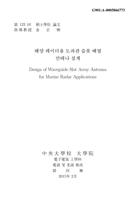
Title Page
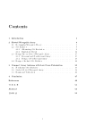
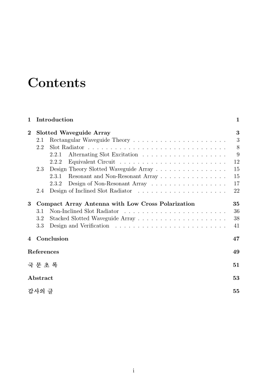
Contents
Chapter 1. Introduction 8
Chapter 2. Slotted Waveguide Array 10
2.1. Rectangular Waveguide Theory 10
2.2. Slot Radiator 15
2.2.1. Alternating Slot Excitation 16
2.2.2. Equivalent Circuit 19
2.3. Design Theory Slotted Waveguide Array 22
2.3.1. Resonant and Non-Resonant Array 22
2.3.2. Design of Non-Resonant Array 24
2.4. Design of Inclined Slot Radiator 29
Chapter 3. Compact Array Antenna with Low Cross Polarization 42
3.1. Non-Inclined Slot Radiator 43
3.2. Stacked Slotted Waveguide Array 45
3.3. Design and Verification 48
Chapter 4. Conclusion 54
References 56
국문초록 58
Abstract 60
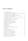
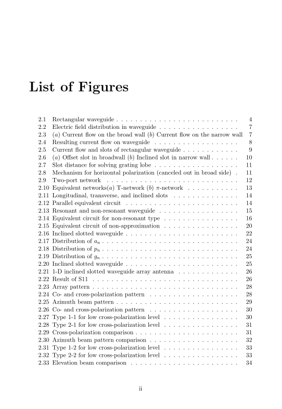
Figure 2.1: Rectangular waveguide 11
Figure 2.2: Electric field distribution in waveguide 14
Figure 2.3: (a) Current flow on the broad wall (b) Current flow on the narrow wall 14
Figure 2.4: Resulting current flow on waveguide 15
Figure 2.5: Current flow and slots of rectangular waveguide 16
Figure 2.6: (a) Offset slot in broadwall (b) Inclined slot in narrow wall 17
Figure 2.7: Slot distance for solving grating lobe 18
Figure 2.8: Mechanism for horizontal polarization (canceled out in broad side) 18
Figure 2.9: Two-port network 19
Figure 2.10: Equivalent networks 20
Figure 2.11: Longitudinal, transverse, and inclined slots 21
Figure 2.12: Parallel equivalent circuit 21
Figure 2.13: Resonant and non-resonant waveguide 22
Figure 2.14: Equivalent circuit for non-resonant type 23
Figure 2.15: Equivalent circuit of non-approximation 27
Figure 2.16: Inclined slotted waveguide 29
Figure 2.17: Distribution of αn(이미지참조) 31
Figure 2.18: Distribution of pn(이미지참조) 31
Figure 2.19: Distribution of gn(이미지참조) 32
Figure 2.20: Inclined slotted waveguide 32
Figure 2.21: 1-D inclined slotted waveguide array antenna 33
Figure 2.22: Result of S11 33
Figure 2.23: Array pattern 35
Figure 2.24: Co- and cross-polarization pattern 35
Figure 2.25: Azimuth beam pattern 36
Figure 2.26: Co- and cross-polarization pattern 37
Figure 2.27: Type 1-1 for low cross-polarization level 37
Figure 2.28: Type 2-1 for low cross-polarization level 38
Figure 2.29: Cross-polarization comparison 38
Figure 2.30: Azimuth beam pattern comparison 39
Figure 2.31: Type 1-2 for low cross-polarization level 40
Figure 2.32: Type 2-2 for low cross-polarization level 40
Figure 2.33: Elevation beam comparison 41
Figure 3.1: Excitation wire way for low cross-polarization 43
Figure 3.2: Perturbation way for low cross-polarization 44
Figure 3.3: Etching 45
Figure 3.4: (a) Before slot insertion (b) After integration 46
Figure 3.5: Smith chart 01 46
Figure 3.6: Metal cover 47
Figure 3.7: Smith chart 02 47
Figure 3.8: gn and Ls(이미지참조) 48
Figure 3.9: Power divider 49
Figure 3.10: S11, S21, S31 and S41 of power divider 49
Figure 3.11: Overall design 50
Figure 3.12: Results of S11 and S21 51
Figure 3.13: Azimuth beam pattern 51
Figure 3.14: Cross-polarization comparison 52
Figure 3.15: Elevation beam pattern 53
ABCD 매트릭스를 이용하여 트레블링 웨이브 어레이 안테나의 병렬로 연결된 컨덕턴스와 트랜스미션라인과 주파수에 따른 S11을 쉽고, 효율적으로 계산하였다. 이에 기반하여 기울임 웨이브가이드 슬롯 어레이 안테나를 디자인 하였고 리턴로스, 안테나의 방사특징이 디자인 이론을 이용하여 계산하였다. 그결과 해양레이더안테나의 요구조건에 만족하는 안테나 빔폭과 대역폭을 얻을 수 있었다. 하지만 크로스폴라리제이션 레벨이 너무 높아서 전체적인 사이드로브레벨이 증가하는 특성을 보였다. 크로스폴라라이제이션 레벨을 낮추고자 웨이브가이드에 폴라라이져가 추가적으로 부착되어있는 구조가 소개되었다. 이로인하여 크로스폴라라이제이션 레벨이 기존의 구조보다 20 dB가 더 낮게 나와서 전체적인 사이드로브가 낮아져 안테나의 요구조건에 만족을 하였다.
다음으로, 크로스폴라라이제이션 레벨을 더욱더 낮추기 위해서 기울임이 없는 슬롯구조의 웨이브가이드 어레이가 제시되었다. 유전체의 양쪽면에 스트립을 에칭한 유전체를 슬롯안으로 삽입하였다. 이 구조를 사용함으로써, 폴라라이저구조보다 20 dB를 더 감소시켜서 좋은 성능을 내었다.
마지막으로, 안테나의 고도방향의 요구조건을 만족시키기 위해, 기존의 플래어드 혼 구조대신 3개의 동일한 웨이브가이드 어레이를 스택하는 방법을 제시하였다. 이 구조로 인하여 해양레이더 안테나의 고도방향의 요구조건을 만족시킴은 물론 안테나의 크기역시 상당히 줄어들었다.*표시는 필수 입력사항입니다.
| 전화번호 |
|---|
| 기사명 | 저자명 | 페이지 | 원문 | 기사목차 |
|---|
| 번호 | 발행일자 | 권호명 | 제본정보 | 자료실 | 원문 | 신청 페이지 |
|---|
도서위치안내: / 서가번호:

우편복사 목록담기를 완료하였습니다.
*표시는 필수 입력사항입니다.
저장 되었습니다.
