
 대표어
대표어
권호기사보기
| 기사명 | 저자명 | 페이지 | 원문 | 기사목차 |
|---|
결과 내 검색
동의어 포함
Title Page
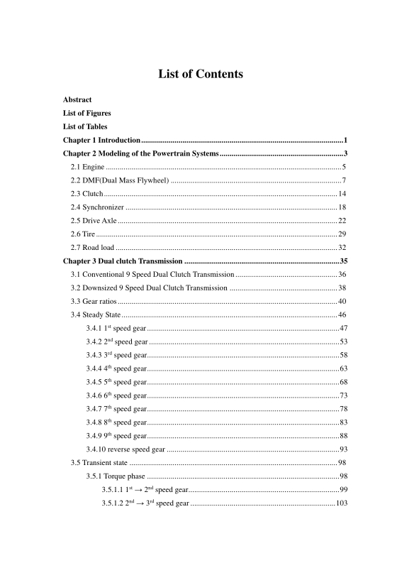
Contents
초록 6
Chapter 1. Introduction 12
Chapter 2. Modeling of the Powertrain Systems 14
2.1. Engine 16
2.2. DMF(Dual Mass Flywheel) 18
2.3. Clutch 25
2.4. Synchronizer 29
2.5. Drive Axle 33
2.6. Tire 40
2.7. Road load 43
Chapter 3. Dual clutch Transmission 46
3.1. Conventional 9 Speed Dual Clutch Transmission 47
3.2. Downsized 9 Speed Dual Clutch Transmission 49
3.3. Gear Ratios 51
3.4. Steady State 57
3.4.1. 1st Speed Gear(이미지참조) 58
3.4.2. 2nd Speed Gear(이미지참조) 64
3.4.3. 3rd Speed Gear(이미지참조) 69
3.4.4. 4th Speed Gear(이미지참조) 74
3.4.5. 5th Speed Gear(이미지참조) 79
3.4.6. 6th Speed Gear(이미지참조) 84
3.4.7. 7th Speed Gear(이미지참조) 89
3.4.8. 8th Speed Gear(이미지참조) 94
3.4.9. 9th Speed Gear(이미지참조) 99
3.4.10. Reverse Speed Gear 104
3.5. Transient State 109
3.5.1. Torque Phase 109
3.5.2. Inertia Phase 140
Chapter 4. Simulation and Results 171
4.1. The Downsized 9 Speed Dual Clutch Performance 171
4.2. Driving Performance 173
4.3. Power mode 180
4.4. Economic mode 183
4.5. Normal mode 186
4.6. Fuel consumption 189
Chapter 5. Conclusion 195
References 198
ABSTRACT 199
Fig. 2.1. Configuration of DMF 18
Fig. 2.2. DMF system 19
Fig. 2.3. DMF model 20
Fig. 2.4. Bond graph of the DMF model 21
Fig. 2.5. Configuration of the dual multi-plate clutch 26
Fig. 2.6. multi-plate clutch model 26
Fig. 2.7. Configuration of synchronizer 29
Fig. 2.8. synchronizer model 30
Fig. 2.9. Drive axle model 33
Fig. 2.10. Bond graph of the drive axle model 35
Fig. 2.11. Tire model 41
Fig. 3.1. Configuration of the Conventional 9 Speed Dual Clutch Transmission 47
Fig. 3.2. Configuration of the downsized 9 Speed DCT 49
Fig. 3.3. Geometrical gear steps 53
Fig. 3.4. Progressive gear steps 55
Fig. 3.5. 9 speed DCT VS 7 speed DCT in Progressive gear steps 56
Fig. 3.6. Power flow of the 1st speed gear(이미지참조) 58
Fig. 3.7. Bond graph of the 1st speed gear(이미지참조) 59
Fig. 3.8. Power flow of the 2nd speed gear(이미지참조) 64
Fig. 3.9. Bond graph of the 2nd speed gear(이미지참조) 65
Fig. 3.10. Power flow of the 3rd speed gear(이미지참조) 69
Fig. 3.11. Bond graph of the 3rd speed gear(이미지참조) 70
Fig. 3.12. Power flow of the 4th speed gear(이미지참조) 74
Fig. 3.13. Bond graph of the 4th speed gear(이미지참조) 75
Fig. 3.14. Power flow of the 5th speed gear(이미지참조) 79
Fig. 3.15. Bond graph of the 5th speed gear(이미지참조) 80
Fig. 3.16. Power flow of the 6th speed gear(이미지참조) 84
Fig. 3.17. Bond graph of the 6th speed gear(이미지참조) 85
Fig. 3.18. Power flow of the 7th speed gear(이미지참조) 89
Fig. 3.19. Bond graph of the 7th speed gear(이미지참조) 90
Fig. 3.20. Power flow of the 8th speed gear(이미지참조) 94
Fig. 3.21. Bond graph of the 8th speed gear(이미지참조) 95
Fig. 3.22. Power flow of the 9th speed gear(이미지참조) 99
Fig. 3.23. Bond graph of the 9th speed gear(이미지참조) 100
Fig. 3.24. Power flow of the R speed gear 104
Fig. 3.25. Bond graph of the R speed gear 105
Fig. 3.26. Power flow of the 1st → 2nd speed gear(이미지참조) 110
Fig. 3.27. Bond graph of the 1st → 2nd speed gear(이미지참조) 111
Fig. 3.28. Power flow of the 2nd → 3rd speed gear(이미지참조) 114
Fig. 3.29. Bond graph of the 2nd → 3rd speed gear(이미지참조) 115
Fig. 3.30. Power flow of the 3rd → 4th speed gear(이미지참조) 118
Fig. 3.31. Bond graph of the 3th → 4th speed gear(이미지참조) 119
Fig. 3.32. Power flow of the 4th → 5th speed gear(이미지참조) 122
Fig. 3.33. Bond graph of the 4th → 5th speed gear(이미지참조) 123
Fig. 3.34. Power flow of the 5th → 6th speed gear(이미지참조) 126
Fig. 3.35. Bond graph of the 5th → 6th speed gear(이미지참조) 127
Fig. 3.36. Power flow of the 6th → 7th speed gear(이미지참조) 130
Fig. 3.37. Bond graph of the 6th → 7th speed gear(이미지참조) 131
Fig. 3.38. Power flow of the 7th → 8th speed gear(이미지참조) 134
Fig. 3.39. Bond graph of the 7th → 8th speed gear(이미지참조) 135
Fig. 3.40. Power flow of the 1st → 2nd speed gear(이미지참조) 141
Fig. 3.41. Bond graph of the 1st → 2nd speed gear(이미지참조) 142
Fig. 3.42. Power flow of the 2nd → 3rd speed gear(이미지참조) 145
Fig. 3.43. Bond graph of the 2nd → 3rd speed gear(이미지참조) 146
Fig. 3.44. Power flow of the 3rd → 4th speed gear(이미지참조) 149
Fig. 3.45. Bond graph of the 3rd → 4th speed gear(이미지참조) 150
Fig. 3.46. Power flow of the 4th → 5th speed gear(이미지참조) 153
Fig. 3.47. Bond graph of the 4th → 5th speed gear(이미지참조) 154
Fig. 3.48. Power flow of the 5th → 6th speed gear(이미지참조) 157
Fig. 3.49. Bond graph of the 5th → 6th speed gear(이미지참조) 158
Fig. 3.50. Power flow of the 6th → 7th speed gear(이미지참조) 161
Fig. 3.51. Bond graph of the 6th → 7th speed gear(이미지참조) 162
Fig. 3.52. Power flow of the 7th → 8th speed gear(이미지참조) 165
Fig. 3.53. Bond graph of the 7th → 8th speed gear(이미지참조) 166
Fig. 4.1. Clutch1 and clutch2 torque 171
Fig. 4.2. Traction force of the steps 174
Fig. 4.3. Shift schedule of the power mode 175
Fig. 4.4. BSFC of the steps 176
Fig. 4.5. Shift schedule of the economic mode 177
Fig. 4.6. Velocity, gear position, engine speed at power mode 181
Fig. 4.7. Velocity, gear position, engine speed at economic mode 184
Fig. 4.8. Velocity, gear position, engine speed at normal mode 187
Fig. 4.9. Velocity, distance, fuel consumption at NEDC mode 190
Fig. 4.10. Velocity, distance, fuel consumption at Japanese 1015 mode 193
*표시는 필수 입력사항입니다.
| 전화번호 |
|---|
| 기사명 | 저자명 | 페이지 | 원문 | 기사목차 |
|---|
| 번호 | 발행일자 | 권호명 | 제본정보 | 자료실 | 원문 | 신청 페이지 |
|---|
도서위치안내: / 서가번호:

우편복사 목록담기를 완료하였습니다.
*표시는 필수 입력사항입니다.
저장 되었습니다.
