
 대표어
대표어

권호기사보기
| 기사명 | 저자명 | 페이지 | 원문 | 기사목차 |
|---|
결과 내 검색
동의어 포함
표제지
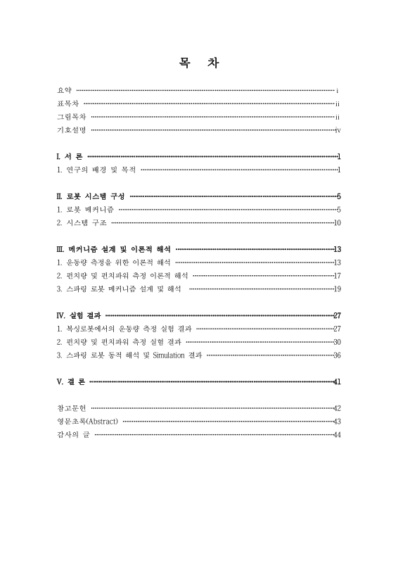
목차
요약 4
기호설명 7
I. 서론 8
1. 연구의 배경 및 목적 8
II. 로봇 시스템 구성 12
1. 로봇 메커니즘 12
1) 스파링 로봇 하체부 플랫폼 메커니즘 12
2) 스파링 로봇 상체부 메커니즘 14
2. 시스템 구조 17
III. 메커니즘 설계 및 이론적 해석 20
1. 운동량 측정을 위한 이론적 해석 20
2. 펀치량 및 펀치파워 측정 이론적 해석 24
3. 스파링 로봇 메커니즘 설계 및 해석 26
1) 병렬 플랫폼의 역기구학 해석 26
2) 스파링 로봇 팔의 동적 해석 30
IV. 실험 결과 34
1. 복싱로봇에서의 운동량 측정 실험 결과 34
2. 펀치량 및 펀치파워 측정 실험 결과 37
3. 스파링 로봇 동적 해석 및 Simulation 결과 43
1) 플랫폼 실험적 검증 43
2) 스파링 로봇 팔 동적 해석 및 Simulation 결과값 45
V. 결론 48
참고문헌 49
Abstract 50
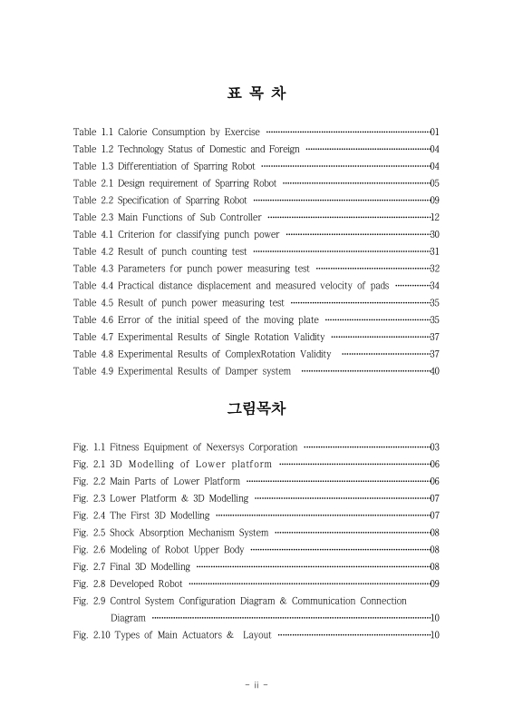
Fig. 1.1. Fitness Equipment of Nexersys Corporation 10
Fig. 2.1. 3D Modelling of Lower platform 13
Fig. 2.2. Main Parts of Lower Platform 13
Fig. 2.3. Lower Platform & 3D Modelling 14
Fig. 2.4. The First 3D Modelling 14
Fig. 2.5. Shock Absorption Mechanism System 15
Fig. 2.6. 3D Modeling of Robot Upper Body 15
Fig. 2.7. Final 3D Modelling 15
Fig. 2.8. Developed Robot 16
Fig. 2.9. Control System Configuration Diagram &... 17
Fig. 2.10. Types of Main Actuators & Layout 17
Fig. 2.11. Main Controller(PC Program) 18
Fig. 2.12. Sub Controller... 18
Fig. 3.1. Relationship between oxygen intake and time 21
Fig. 3.2. Relationship between velocity and time 22
Fig. 3.3. Relationship between VO2 and time 22
Fig. 3.4. VO2 intake measurement... 23
Fig. 3.5. Hall sensor output voltage according to the... 24
Fig. 3.6. Reference Frame of Parallel Platform 26
Fig. 3.7. Floor Plan of Parallel Platform 27
Fig. 3.8. Kinematic Constraint of Parallel Platform 28
Fig. 3.9. Left Side View of Sparring Robot Arm 30
Fig. 3.10. Left Arm 3D Modelling of Sparring Robot Arm 31
Fig. 3.11. Free Body Diagram of Sparring Robot Arm 31
Fig. 3.12. 2D - Two Link of Sparring Robot Arm 32
Fig. 4.1. Experiment on measuring kinetic energy and exercise... 34
Fig. 4.2. Relationship between VO2 and punch bit 35
Fig. 4.3. Relationship between t and punch bit 35
Fig. 4.4. Relationship between ∫ E dt and VO2 36
Fig. 4.5. Equipment for measuring punch power 38
Fig. 4.6. Displacement measurement of the moving plate 40
Fig. 4.7. Speed measurement of the moving plate 41
Fig. 4.8. Stress Analysis of Waist(Von mieses stress) 43
Fig. 4.9. Parameter Measure of Robot Arm 45
Fig. 4.10. Joint 1 Torque using Euler-Lagrangian Formulation 45
Fig. 4.11. Joint 2 Torque using Euler-Lagrangian Formulation 46
Fig. 4.12. Modelling Simulation of Robot 46
Fig. 4.13. Yaw Joint Torque(No Damper) 47
Fig. 4.14. Yaw Joint Torque(Using Damper) 47
*표시는 필수 입력사항입니다.
| 전화번호 |
|---|
| 기사명 | 저자명 | 페이지 | 원문 | 기사목차 |
|---|
| 번호 | 발행일자 | 권호명 | 제본정보 | 자료실 | 원문 | 신청 페이지 |
|---|
도서위치안내: / 서가번호:

우편복사 목록담기를 완료하였습니다.
*표시는 필수 입력사항입니다.
저장 되었습니다.
