
 대표어
대표어


권호기사보기
| 기사명 | 저자명 | 페이지 | 원문 | 기사목차 |
|---|
결과 내 검색
동의어 포함
목차
[표제지 등]=0,1,2
제출문=0,3,1
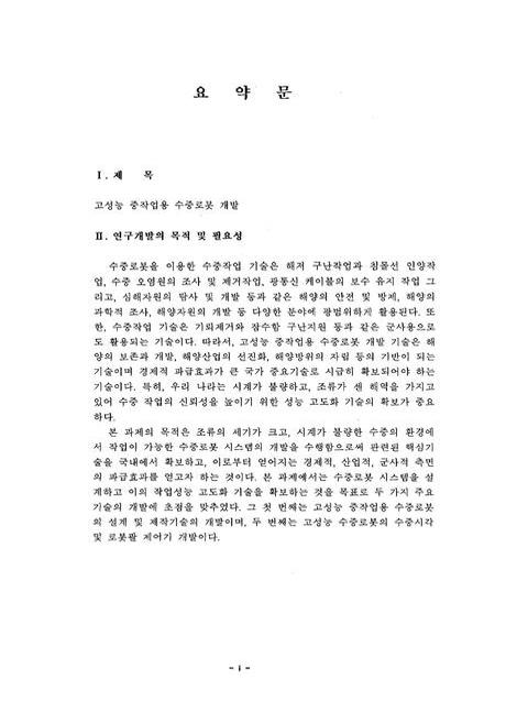
요약문=i,4,19
목차=xx,23,3
표목차=xxiii,26,2
그림목차=xxv,28,6
제1장 서론=1,34,3
제2장 국내외 기술개발 현황=4,37,1
2.1절 수중로봇의 역사=4,37,1
2.2절 국외 기술 개발동향=4,37,16
2.3절 국내 기술 개발동향=19,52,4
2.4절 수중로봇 기술의 미래=22,55,3
제3장 수중로봇의 수학적 모델링 및 수치 모의실험=25,58,1
3.1절 ROV 운동의 수학모델=25,58,8
3.2절 ROV의 모의실험의 결과=32,65,25
제4장 중작업 수중로봇의 용량계산 및 선형ㆍ배치 상세설계=57,90,1
4.1절 중작업 수중로봇의 선형 및 배치 설계=57,90,5
4.2절 시스템의 용량추정=62,95,7
4.3절 추진기 설계=68,101,4
4.4절 프레임의 Scantling 및 중량계산=71,104,6
4.5절 중량 및 소요부력 계산=76,109,4
제5장 시스템 사양확정 및 주요장비 선정=80,113,1
5.1절 시스템 사양확정=80,113,6
5.2절 주요장비 선정=85,118,6
제6장 유압시스템의 상세 설계=91,124,1
6.1절 유압시스템의 구성=91,124,2
6.2절 주요 유압 장치의 사양 설계=92,125,3
6.3절 유압시스템의 설계=95,128,2
6.4절 유압계통 상세설계=96,129,5
6.5절 유압시스템의 설계도면 및 도면 설명=100,133,11
제7장 전기ㆍ전자 시스템 상세설계=111,144,1
7.1절 전기ㆍ전자 시스템의 구성=111,144,5
7.2절 주제어 시스템 상세설계=115,148,8
7.3절 인터페이스 시스템 상세설계=123,156,14
7.4절 광통신 시스템 상세설계=137,170,19
7.5절 Umbilical 및 수상제어 시스템 상세설계=155,188,4
제8장 ISE Design Review=159,192,9
제9장 운용소프트웨어의 설계 및 시뮬레이터 개발=168,201,1
9.1절 운용소프트웨어 실현을 위한 개발환경의 구축=168,201,5
9.2절 계층구조 소프트웨어 설계=173,206,6
9.3절 VxWorks를 근간으로 한 소프트웨어 구조 상세설계=179,212,4
9.4절 중작업 수중로봇 운용 시뮬레이터 개발=183,216,22
제10장 입체영상 시스템 설계=205,238,1
10.1절 입체영상 시스템 개요=205,238,2
10.2절 수중 입체카메라 제작=206,239,18
10.3절 Power cepstrum을 이용한 자세 및 시차정보 추출=224,257,4
10.4절 입체카메라 자동 주시각제어 실험=227,260,10
10.5절 요약=237,270,1
제11장 수중 매니퓰레이터 제어기=238,271,1
11.1절 선체탑재 수중 로봇팔의 제어기 설계=238,271,12
11.2절 선체운동 보상 제어기 설계=250,283,14
11.3절 수중 Telerobotic Manipulator 제어기 설계=264,297,18
11.4절 원격제어를 위한 통신 프로그램=281,314,3
11.5절 사용자 인터페이스(GUI) 개발=283,316,7
11.6절 원격조종 제어 알고리즘=289,322,11
11.7절 요약=299,332,2
제12장 연구개발목표 달성도 및 대외기여도=301,334,1
12.1절 연구개발목표 달성도=301,334,3
12.2절 관련분야 기술발전에의 기여도=303,336,1
제13장 연구개발결과의 활용계획=304,337,1
13.1절 추가연구의 필요성=304,337,1
13.2절 연구개발 결과의 활용계획=305,338,2
제14장 결론=307,340,4
참고문헌=311,344,3
부록=314,347,66
그림2.1 Perry Tritech's Triton 25=5,38,1
Fig.2.1 Perry Tritech's Triton 25=5,38,1
그림2.2 ISE's ROPOS=9,42,1
Fig.2.2 ISE's ROPOS=9,42,1
그림2.3 WHOI's JASON=10,43,1
Fig.2.3 WHOI's JASON=10,43,1
그림2.4 MBARI's Tiburon=11,44,1
Fig.2.4 MBARI's Tiburon=11,44,1
그림2.5 JAMSTEC's KAIKO=12,45,1
Fig.2.5 JAMSTEC's KAIKO=12,45,1
그림2.6 하와이대학의 무인잠수정 SAUVIM 및 이에 장착된 Ansaldo 수중 로봇팔=16,49,1
Fig.2.6 SAUVIM & Ansaldo underwater manipulator of Univ. of Hawaii=16,49,1
그림2.7 SAUVIM 에 장착된 Ansaldo 수중로봇팔의 설계 도면=16,49,1
Fig.2.7 Drawing of Ansaldo manipulator for SAUVIM=16,49,1
그림2.8 Ansaldo 수중로봇팔의 압력보상장치 도면=17,50,1
Fig.2.8 Drawing of Pressure compensator for Ansaldo manipulator=17,50,1
그림2.9 Ansaldo 수중로봇팔의 실험실 작동 시험 전경=17,50,1
Fig.2.9 Operation test of Ansaldo manipulator=17,50,1
그림2.10 Ansaldo 수중로봇팔의 END-effector 및 6자유도 힘-토오크 센서=18,51,1
Fig.2.10 End-effector & 6 DOF force-torque sensor of Ansaldo manipulator=18,51,1
그림2.11 Ansaldo 수중로봇팔의 압력보상장치 사진=18,51,1
Fig.2.11 Pressure compensator of underwater manipulator 'Ansaldo'=18,51,1
그림2.12 SAUVIM 제어기의 항법 및 로봇관 제어기 블럭선도=19,52,1
Fig.2.12 Block diagram of navigation and arm control system for SAUVIM=19,52,1
그림2.13 해양250 유인잠수정=19,52,1
Fig.2.13 Manned underwater vehicle Ocean250=19,52,1
그림2.14 CROV300=20,53,1
Fig.2.14 CROV300=20,53,1
그림2.15 VORAM AUV=20,53,1
Fig.2.15 VORAM AUV=20,53,1
그림2.16 중작업 ROV=20,53,1
Fig.2.16 Heavy duty ROV=20,53,1
그림2.17 반자율무인잠수정 SAUV=21,54,1
Fig.2.17 Semi-autonomous underwater vehicle SAUV=21,54,1
그림2.18 OKPO6000 AUV=21,54,1
Fig.2.18 OKPO6000 AUV=21,54,1
그림3.1 좌표축계=26,59,1
Fig.3.1 Coordinate system=26,59,1
그림3.2 Relation between Body-fixed and Space-fixed coordinates (Eulerian Angles)=33,66,1
Fig.3.2 Relation between Body-fixed and Space-fixed coordinates (Eulerian Angles)=33,66,1
그림3.3 Location of Thrusters=35,68,1
Fig.3.3 Location of Thrusters=35,68,1
그림3.4 Hydrodynamic Characteristics for the MURS 300 MK II=36,69,1
Fig.3.4 Hydrodynamic Characteristics for the MURS 300 MK II=36,69,1
그림3.5 The Motion Responses of the ROV without Automatic control for a step input of the horizontal thrust=37,70,1
Fig.3.5 The Motion Responses of the ROV without Automatic control for a step input of the horizontal thrust=37,70,1
그림3.5 Continued=38,71,1
Fig.3.5 Continued=38,71,1
그림3.6 The Motion Responses of the ROV with Automatic control for a step input of the horizonal thrust=39,72,2
Fig.3.6 The Motion Responses of the ROV with Automatic control for a step input of the horizonal thrust=39,72,2
그림3.7 Trajectory of the ROV with/without Automatic Control for a step input of the horizonal thrust=41,74,1
Fig.3.7 Trajectory of the ROV with/without Automatic Control for a step input of the horizonal thrust=41,74,1
그림3.8 The Motion Responses of the ROV without Automatic control for a step input of the side thrust=42,75,2
Fig.3.8 The Motion Responses of the ROV without Automatic control for a step input of the side thrust=42,75,2
그림3.9 The Motion Responses of the ROV with Automatic control for a step input of the side thrust=44,77,2
Fig.3.9 The Motion Responses of the ROV with Automatic control for a step input of the side thrust=44,77,2
그림3.10 Trajectory of the ROV with/without Automatic Control for a step input of the side thrust=46,79,1
Fig.3.10 Trajectory of the ROV with/without Automatic Control for a step input of the side thrust=46,79,1
그림3.11 The Motion Responses of the ROV without Automatic control for a step input of the vertical thrust=47,80,2
Fig.3.11 The Motion Responses of the ROV without Automatic control for a step input of the vertical thrust=47,80,2
그림3.12 Trajectory of the ROV without Automatic control for the vertical thrust=49,82,1
Fig.3.12 Trajectory of the ROV without Automatic control for the vertical thrust=49,82,1
그림3.13 The Motion Responses of the ROV with Automatic control for a step input of the turning moment=50,83,2
Fig.3.13 The Motion Responses of the ROV with Automatic control for a step input of the turning moment=50,83,2
그림3.14 The Motion Responses of the ROV without automatic control for a pulse input of vertical thrust=52,85,1
Fig.3.14 The Motion Responses of the ROV without automatic control for a pulse input of vertical thrust=52,85,1
그림3.15 The Motion Responses of the ROV with automatic control for a pulse input of vertical thrust=53,86,1
Fig.3.15 The Motion Responses of the ROV with automatic control for a pulse input of vertical thrust=53,86,1
그림3.16 Trajectory of the ROV with/without automatic control for a pulse input of vertical thrust=54,87,1
Fig.3.16 Trajectory of the ROV with/without automatic control for a pulse input of vertical thrust=54,87,1
그림3.17 The Motion Responses of the ROV with automatic control for a pulse input of turning moment=55,88,1
Fig.3.17 The Motion Responses of the ROV with automatic control for a pulse input of turning moment=55,88,1
그림4.18 HROV의 3차원 도면의 Rendering=58,91,1
Fig.4.18 Rendering of HROV 3D drawing=58,91,1
그림4.19 3차원 배치도면=59,92,1
Fig.4.19 3 dimensional arrangement=59,92,1
그림4.20 중작업용 ROV의 측면도=61,94,1
Fig.4.20 Side view of heavy duty ROV=61,94,1
그림4.21 중작업용 ROV의 상면도=61,94,1
Fig.4.21 Top view of heavy duty ROV=61,94,1
그림4.22 속도의 증가에 따른 저항의 변화=63,96,1
Fig.4.22 Resist variation with increasing speed=63,96,1
그림4.23 운용 수심의 변화에 따른 저항의 변화=63,96,1
Fig.4.23 Resist variation with operating depth=63,96,1
그림4.24 주요 부재의 단면도=72,105,1
Fig.4.24 Cross sectional view of ingredients=72,105,1
그림4.25 Framel의 부재 위치 및 좌표계=73,106,1
Fig.4.25 Position and coordinate system of Framel ingredients=73,106,1
그림4.26 Frame2의 부재 위치 및 좌표계=75,108,1
Fig.4.26 Position and coordinate system of Frame2 ingredients=75,108,1
그림4.27 부력재의 용적 계산을 위한 분류=79,112,1
Fig.4.27 Classification of buoyant materials for volume estimation=79,112,1
그림5.1 추진기 모터 : Rexroth사 AA2FM32=86,119,1
Fig.5.1 Hydraulic thrust motor: Rexroth AA2FM32=86,119,1
그림5.2 유압펌프 : Rexroth사 KT4017-4=86,119,1
Fig.5.2 Hydraulic pump: Rexroth KT4017-4=86,119,1
그림5.3 슬래이브 매니퓰레이터 시뮬레이션용 DADS 모델=87,120,1
Fig.5.3 DADS simulation model of 7-function slave manipulator=87,120,1
그림5.4 HROV에 사용될 7축 슬래이브 매니퓰레이터=88,121,1
Fig.5.4 7-function slave manipulator for HROV=88,121,1
그림5.5 SIT 카메라(OE1324)=89,122,1
Fig.5.5 SIT Camera(OE1324)=89,122,1
그림6.1 유압시스템의 메인 블록 다이어그램=105,138,1
Fig.6.1 Main block diagram of the hydraulic system=105,138,1
그림6.2 수중로봇 시스템의 유압회로도=106,139,1
Fig.6.2 Circuit of the hydraulic system for underwater robot system=106,139,1
그림6.3 추진기 제어시스템의 회로도=107,140,1
Fig.6.3 Circuit of the propulsion control system=107,140,1
그림6.4 7축 매니퓰레이터 시스템의 유압회로도=108,141,1
Fig.6.4 Hydraulic circuit of 7-function manipulator=108,141,1
그림6.5 5축 매니퓰레이터 시스템의 유압회로도=109,142,1
Fig.6.5 Hydraulic circuit of 5-function manipulator=109,142,1
그림6.6 보조 시스템의 유압회로도=110,143,1
Fig.6.6 Hydraulic circuit of auxiliary system=110,143,1
그림7.1 수상 전기시스템의 구성=112,145,1
Fig.7.1 Configuration of the surface electric system=112,145,1
그림7.2 수중 전기시스템의 구성=114,147,1
Fig.7.2 Configuration of the subsea electric system=114,147,1
그림7.3 수중 제어시스템의 하드웨어 구성=115,148,1
Fig.7.3 Configuration of the hardware for the subsea control system=115,148,1
그림7.4 HROV의 제어시스템 구성=116,149,1
Fig.7.4 Configuration of HROV control system=116,149,1
그림7.5 전기ㆍ전자 시스템의 인터페이스 구성도=123,156,1
Fig.7.5 Interface for the electric and electronic system=123,156,1
그림7.6 Junction Box Interconnection 상세설계=125,158,1
Fig.7.6 Detail design of the junction box interconnection=125,158,1
그림7.7 Digital I/O 인터페이스=129,162,1
Fig.7.7 Digital I/O interface=129,162,1
그림7.8 아날로그 출력 및 시리얼 인터페이스=131,164,1
Fig.7.8 Analog output and a serial interface=131,164,1
그림7.9 Digital I/O Distribution Board 인터페이스=133,166,1
Fig.7.9 Interface of the digital I/O distribution board=133,166,1
그림7.10 Signal Conditioning 보드 인터페이스=135,168,1
Fig.7.10 Interface of the signal conditioning board=135,168,1
그림7.11 광통신 시스템의 기본구성=138,171,1
Fig.7.11 Basic configuration of the optic communication system=138,171,1
그림7.12 레이저 다이오드의 구동회로=139,172,1
Fig.7.12 Driving circuit of the laser diode=139,172,1
그림7.13 시분할 다중화 방식(TDM)의 다중화기 구조=141,174,1
Fig.7.13 Multiplexing structure of TDM method=141,174,1
그림7.14 주파수 분할 다중화방식(FDM)=142,175,1
Fig.7.14 Concepts of FDM method=142,175,1
그림7.15 파장 분할 다중화방식(WDM)=143,176,1
Fig.7.15 Concepts of WDM method=143,176,1
그림7.16 펄스 진폭변조(PAM)=144,177,1
Fig.7.16 Concepts of PAM method=144,177,1
그림7.17 펄스코드 변조방식(PCM)=145,178,1
Fig.7.17 Concepts of PCM method=145,178,1
그림7.18 FDM을 이용한 광통신 시스템 개념설계=147,180,1
Fig.7.18 Conceptual design of the optic communication system using FDM=147,180,1
그림7.19 TDM을 이용한 광통신 시스템 개념설계=148,181,1
Fig.7.19 Conceptual design of the optic communication system using TDM=148,181,1
그림7.20 HROV의 광통신 시스템 구성도=149,182,1
Fig.7.20 Configuration of the optic communication system for HROV=149,182,1
그림7.21 아날로그 강도변조방식(IM)의 전송원리=150,183,1
Fig.7.21 Concepts of the analog IM method=150,183,1
그림7.22 광 Video Link 모듈의 구성도=150,183,1
Fig.7.22 Configuration of the optic video module=150,183,1
그림7.23 광 Video Link 모듈=152,185,1
Fig.7.23 Photo of the optic video module=152,185,1
그림7.24 광 Data Link의 블록 다이어그램=153,186,1
Fig.7.24 Block diagram of the optic data module=153,186,1
그림7.25 광 Data Link를 사용하여 구성한 회선 예=154,187,1
Fig.7.25 Example of the system configuration using the optic data module=154,187,1
그림7.26 광 Data Link 모듈=154,187,1
Fig.7.26 Photo of the optic data module=154,187,1
그림7.27 HROV Umbilical 케이블의 구성 개념도=156,189,1
Fig.7.27 Conceptual configuration of HROV's umbilical cable=156,189,1
그림7.28 수상제어용 콘솔 시스템의 상세설계=157,190,1
Fig.7.28 Detail design of the surface control console system=157,190,1
그림7.29 수상제어 콘솔 시스템의 3D View=157,190,1
Fig.7.29 3D view of the surface control console system=157,190,1
그림9.1 HROV의 운용 S/W 개발 환경=168,201,1
Fig.9.1 Development environment of HROV operating S/W=168,201,1
그림9.2 Real-Time System=170,203,1
Fig.9.2 Real-Time System=170,203,1
그림9.3 Serial을 통한 Host와 Target 간의 연결=171,204,1
Fig.9.3 Inter-connection between Host and Target with serial comm.=171,204,1
그림9.4 Ethernet을 통한 Host와 Target의 연결=171,204,1
Fig.9.4 Inter-connection between Host and Target with ethernet=171,204,1
그림9.5 Host와 Target과의 통신개념=172,205,1
Fig.9.5 Concept of communication between Host and Target=172,205,1
그림9.6 HROV 소프트웨어의 구성=173,206,1
Fig.9.6 Configuration of HROV software=173,206,1
그림9.7 수상제어 소프트웨어의 구성=174,207,1
Fig.9.7 Configuration of surface control software=174,207,1
그림9.8 H/W I/F 및 수상 제어소프트웨어의 구조=174,207,1
Fig.9.8 Interface of surface H/W and structure of surface control software=174,207,1
그림9.9 디지털 입출력 항목의 정의=175,208,1
Fig.9.9 Digital I/O definition=175,208,1
그림9.10 아날로그 입출력 정의=175,208,1
Fig.9.10 Analog I/O definition=175,208,1
그림9.11 수상2수중 모듈의 입출력 정의=176,209,1
Fig.9.11 I/O definition of Surface to Sub-sea Module=176,209,1
그림9.12 수중2수상 모듈의 입출력 정의=177,210,1
Fig.9.12 I/O definition of Sub-sea to Surface Module=177,210,1
그림9.13 수중제어 소프트웨어의 구조=178,211,1
Fig.9.13 Structure of sub-sea control software=178,211,1
그림9.14 하드웨어 I/F 및 수중제어 소프트웨어=178,211,1
Fig.9.14 Hardware I/F and sub-sea control software=178,211,1
그림9.15 Task States of the Multi-tasking Kernel=181,214,1
Fig.9.15 Task States of the Multi-tasking Kernel=181,214,1
그림9.16 HROV의 VxWorks를 이용한 소프트웨어 구조=182,215,1
Fig.9.16 Structure design of HROV software using VxWorks=182,215,1
그림9.17 The Flow Chart of Visual Simulation=185,218,1
Fig.9.17 The Flow Chart of Visual Simulation=185,218,1
그림9.18 Sample View of ROV_View Ver1.0=187,220,2
Fig.9.18 Sample View of ROV_View Ver1.0=187,220,2
그림9.19 Sample View of ROV under Operation=189,222,1
Fig.9.19 Sample View of ROV under Operation=189,222,1
그림9.20 The IRIS Performer Library Hierarchy=190,223,1
Fig.9.20 The IRIS Performer Library Hierarchy=190,223,1
그림9.21 The Relationship of IRIS Performer to Database Formats=192,225,1
Fig.9.21 The Relationship of IRIS Performer to Database Formats=192,225,1
그림9.22 Import Procedures of Various Database=193,226,1
Fig.9.22 Import Procedures of Various Database=193,226,1
그림9.23 Sample of Visual Simulation made by Vega=194,227,1
Fig.9.23 Sample of Visual Simulation made by Vega=194,227,1
그림9.24 Sample of Visual Simulation made by Vega=194,227,1
Fig.9.24 Sample of Visual Simulation made by Vega=194,227,1
그림9.25 System Diagram of Vega Application=195,228,1
Fig.9.25 System Diagram of Vega Application=195,228,1
그림9.26 User Interface, Lynx for Vega=200,233,1
Fig.9.26 User Interface, Lynx for Vega=200,233,1
그림9.27 Vega class Hierarchy=201,234,1
Fig.9.27 Vega class Hierarchy=201,234,1
그림9.28 Workflow of I/Geovec Head-Lip Digitizing System=203,236,1
Fig.9.28 Workflow of I/Geovec Head-Lip Digitizing System=203,236,1
그림9.29 Workflow of Map Digitizing=204,237,1
Fig.9.29 Workflow of Map Digitizing=204,237,1
그림10.1 수평이동축 입체카메라의 개념도=207,240,1
Fig.10.1 Conceptual diagram of the horizontal-moving axis stereo camera=207,240,1
그림10.2 수평이동축 입체카메라 (KASS-M2)의 구조=208,241,1
Fig.10.2 Structure of horizontal-moving stereo camera(KASS-M2)=208,241,1
그림10.3 수평이동축 입체카메라의 제어기 구성=208,241,1
Fig.10.3 Configuration of control system for horizontal-moving axis stereo camera=208,241,1
그림10.4 수평이동축 입체카메라 (KASS-M2) (a)평면사진, (b)측면사진=209,242,1
Fig.10.4 Horizontal-moving axis stereo camera(KASS-M2)=209,242,1
그림10.5 평행식 스테레오 카메라의 기하학적 기호 정의=210,243,1
Fig.10.5 Definition of geometric notation and symbols of parallel stereo camera=210,243,1
그림10.6 개선된 단동형 수중 스테레오 카메라의 작동 개념도=211,244,1
Fig.10.6 Conceptual diagram of an improved underwater stereo camera=211,244,1
그림10.7 개선된 단동형 수중 스테레오 카메라의 작동 구성도=213,246,1
Fig.10.7 Composition of improved underwater camera=213,246,1
그림10.8 단동형 수중 스테레오 카메라의 방수 장치 구성도=214,247,1
Fig.10.8 Composition of sealing devices for the underwater stereo camera=214,247,1
그림10.9 수중용 입체영상 카메라 설계도=215,248,1
Fig.10.9 Drawings of underwater stereo camera=215,248,1
그림10.10 수중용 입체영상 카메라의 설계도=217,250,1
Fig.10.10 Drawings of underwater stereo camera=217,250,1
그림10.11 제작된 수중용 입체영상 카메라=217,250,1
Fig.10.11 Manufactured underwater stereo image camera=217,250,1
그림10.12 실험용 흑백 패턴=218,251,1
Fig.10.12 Black & white patter for experiment=218,251,1
그림10.13 수중획득영상 1 (주시각거리: 640mm, 물체거리: 640mm)=218,251,1
Fig.10.13 Acquired image in water 1 (vergence distance: 640mm, object distance: 640mm)=218,251,1
그림10.14 수중획득영상 2 (주시각거리: 320mm, 물체거리: 640mm)=219,252,1
Fig.10.14 Acquired image in water 2 (vergence distance: 320mm, object distance: 640mm)=219,252,1
그림10.15 수중획득영상 3 (주시각거리: 960mm, 물체거리: 640mm)=219,252,1
Fig.10.15 Acquired image in water 3 (vergence distance: 960mm, object distance: 640mm)=219,252,1
그림10.16 공기중 획득영상 1 (주시각거리: 640mm, 물체거리: 640mm)=219,252,1
Fig.10.16 Acquired image in air 1 (vergence distance: 640mm, object distance: 640mm)=220,252,1
그림10.17 공기중 획득영상 2 (주시각거리: 320mm, 물체거리: 640mm)=220,253,1
Fig.10.17 Acquired image in air 2 (vergence distance: 320mm, object distance: 640mm)=220,253,1
그림10.18 공기중 획득영상 3 (주시각거리: 960mm, 물체거리: 640mm)=220,253,1
Fig.10.18 Acquired image in air 3 (vergence distance: 960mm, object distance: 640mm)=220,253,1
그림10.19 수중에서의 물체거리 측정=221,254,1
Fig.10.19 Measurement of object distance in water=221,254,1
그림10.20 수중 거리 측정을 위한 기하학적 기호 정의=223,256,1
Fig.10.20 Definition of geometric symbols for measurement of underwater object distance=223,256,1
그림10.21 파워 켑스트럼 정의=224,257,1
Fig.10.21 Definition of power cepstrum=224,257,1
그림10.22 시차 dh=8, dv=8 (이미지참조)픽셀의 샘플 입체영상에 대한 켑스트럼=225,258,1
Fig.10.22 Power cepstrum for sampled stereo image with parallax dh=8, dv=8(이미지참조) pixel=225,258,1
그림10.23 시차 dh=16, dv=16(이미지참조) 픽셀의 샘플 입체영상에 대한 power cepstrum=226,259,1
Fig.10.23 Power cepstrum for sampled stereo image with parallax dh=16, dv=16(이미지참조) pixel=226,259,1
그림10.24 KASS-M2 자동 주시각 제어를 위해 제안된 일차원 켑스트럼 기반 고속, 고정밀 시차추출 기법=227,260,1
Fig.10.24 KASS-M2 first order cepstrum-based high speed & high precision visual extraction method for automatic vergence control=227,260,1
그림10.25 제안한 주시각 자동 제어 시스템 구성도=227,260,1
Fig.10.25 Configuration of proposed automatic vergence control system=227,260,1
그림10.26 KASS-M2 입체카메라 및 주시각 자동제어 (a) KASS-M2 수평이동축 입체카메라, (b)주시각 자동제어 시스템=228,261,1
Fig.10.26 KASS-M2 stereo camera and automatic vergence control=228,261,1
그림10.27 거리 0.5m에 주시거리를 맞추었을 때 0.5, 1, 1.5, 2m 위치의 입체영상 (a) 0.5m의 입체영상, (b)1m의 입체영상, (c) 1.5m의 입체영상 (d) 2m의 입체영상 =229,262,1
Fig.10.27 0.5, 1, 1.5, 2m stereo image with 0.5m vergence distance=229,262,1
그림10.28 거리 1.5m에 주시거리를 맞추었을 때 0.5, 1, 1.5, 2m 위치의 입체영상 (a) 0.5m의 입체영상, (b) 1m의 입체영상, (c) 1.5m 입체영상, (d) 2m의 입체영상=230,263,1
Fig.10.28 0.5, 1, 1.5, 2m stereo image with 1.5m vergence distance=230,263,1
그림10.29 시차에러 비교=232,265,1
Fig.10.29 Comparison of parallax error=232,265,1
그림10.30 시차에러 비교=232,265,1
Fig.10.30 Comparison of parallax error=232,265,1
그림10.31 주시각 제어 과정=234,267,2
Fig.10.31 Process of vergence control=234,267,2
그림10.32 시차량 측정=235,268,1
Fig.10.32 Measurement of parallax=235,268,1
그림10.33 시차량 측정=236,269,1
Fig.10.33 Measurement of parallax=236,269,1
그림10.34 초점 선명도 측정 (a) 분산을 이용한 초점 선명도 측정 (b) 고주파에너지를 이용한 초점 선명도 측정=236,269,1
Fig.10.34 Measurement of focal clearance=236,269,1
그림11.1 2자유도 선체 탑재형 수중 로봇팔=243,276,1
Fig.11.1 2-DOF vehicle mounted underwater manipulator=243,276,1
그림11.2 선체탑재 수중 로봇 팔 (UVMS)의 궤적: 영의 초기변수; 실선-시뮬레이션, 점선-요구궤적=245,278,1
Fig.11.2 Trajectory of vehicle mounted underwater manipulator(UVMS):zero initial variable; solid line - simulation, dotted - reference trajectory=245,278,1
그림11.3 UVMS 조인트 토오크: 영의 초기변수=245,278,1
Fig.11.3 UVMS joint torque : Zero initial variable=245,278,1
그림11.4 추정된 파라메터: 영의 초기변수=246,279,1
Fig.11.4 Estimated parameter: zero initial variable=246,279,1
그림11.5 선체탑재 수중 로봇 팔 (UVMS)의 궤적: 임의의 초기변수; 실선-시뮬레이션, 점선-요구궤적=247,280,1
Fig.11.5 Trajectory of vehicle mounted underwater manipulator(UVMS):non-zero initial variable; solid line - simulation, dotted - reference trajectory=247,280,1
그림11.6 UVMS 조인트 토오크: 임의의 초기변수=247,280,1
Fig.11.6 UVMS jonint torque: zero initial variable=247,280,1
그림11.7 UVMS 조인트 토오크: 임의의 초기변수=248,281,1
Fig.11.7 UVMS jonint torque: non-zero initial variable=248,281,1
그림11.8 임의의 초기변수를 갖는 UVMS의 자세 궤적: 0.5초 시간간격=248,281,1
Fig.11.8 Attitude trajectory of UVMS with non-zero initial variable : 0.5sec interval=248,281,1
그림11.9 임의의 초기변수를 갖는 UVMS의 추정된 파라메터=249,282,1
Fig.11.9 Estimated parameter of UVMS with non-zero initial variable=249,282,1
그림11.10 수중로봇 시스템=251,284,1
Fig.11.10 Underwater robot system=251,284,1
그림11.11 수중로봇 시스템=256,289,1
Fig.11.11 Underwater robot system=256,289,1
그림11.12 외란 관측기 구조=257,290,1
Fig.11.12 Structure of disturbance observer=257,290,1
그림11.13 Manipulator tip position without control=258,291,1
Fig.11.13 Manipulator tip position without control=258,291,1
그림11.14 States of ROV without control=258,291,1
Fig.11.14 States of ROV without control=258,291,1
그림11.15 Manipulator tip position with ROV position controller=259,292,1
Fig.11.15 Manipulator tip position with ROV position controller=259,292,1
그림11.16 States of ROV with ROV position controller=260,293,1
Fig.11.16 States of ROV with ROV position controller=260,293,1
그림11.17 Manipulator tip position with F/T sensor information=260,293,1
Fig.11.17 Manipulator tip position with F/T sensor information=260,293,1
그림11.18 States of ROV with F/T sensor information=261,294,1
Fig.11.18 States of ROV with F/T sensor information=261,294,1
그림11.19 Manipulator tip position with disturbance observer=261,294,1
Fig.11.19 Manipulator tip position with disturbance observer=261,294,1
그림11.20 States of ROV with disturbance observer=262,295,1
Fig.11.20 States of ROV with disturbance observer=262,295,1
그림11.21 5각관절 병렬 기구=265,298,1
Fig.11.21 Mechanism of five-bar parallel link=265,298,1
그림11.22 5각관절 링크 구조=266,299,1
Fig.11.22 Structure of five-bar link=266,299,1
그림11.23 정기구학 해의 다중성=270,303,1
Fig.11.23 Multiplicity of kinematic solution=270,303,1
그림11.24 5각관절 기구에 적용되는 힘과 토오크 성분=272,305,1
Fig.11.24 Force and torque components working five-bar link=272,305,1
그림11.25 정, 역 기구학의 검증=274,307,1
Fig.11.25 Verification of kinematic, inverse-kenematic analysis=274,307,1
그림11.25 정, 역 기구학의 검증 (계속)=275,308,1
Fig.11.25 Verification of kinematic, inverse-kenematic analysis(continued)=275,308,1
그림11.26 주어진 작업=276,309,1
Fig.11.26 Given work=276,309,1
그림11.27 Jacobian 해석 검증=276,309,1
Fig.11.27 Verification of Jacobian analysis=276,309,1
그림11.28 비교대상 기구 구조=277,310,1
Fig.11.28 Structure of compared link=277,310,1
그림11.29 작업공간=278,311,2
Fig.11.29 Working space=278,311,2
그림11.30 정규화된 운동능력 지수=279,312,1
Fig.11.30 Normalized motor ability index=279,312,1
그림11.31 저항능력 지수의 크기=279,312,1
Fig.11.31 Magnitude of resistant capacity index=279,312,1
그림11.32 Fivebar 구조 설계도=280,313,1
Fig.11.32 Drawing of fivebar structure=280,313,1
그림11.33 마스터 코트롤러 제어 시스템의 구성도=281,314,1
Fig.11.33 Configuration of control system ofmaster controller=281,314,1
그림11.34 통신 시스템 구조=282,315,1
Fig.11.34 Structure of communication system=282,315,1
그림11.35 시스템 사이의 연결 관계=282,315,1
Fig.11.35 Inter-system connections=282,315,1
그림11.36 연결형 서비스 작업 절차=283,316,1
Fig.11.36 Procedure of connecting type service work=283,316,1
그림11.37 GUI의 구성: (a) Maser GUI (b) 수중 Slave GUI=286,319,1
Fig.11.37 Configuration of GUI (a) Maser GUI (b) Underwater Slave GUI=286,319,1
그림11.38 Icon 섹션: (a) Slaved의 Icon Section (b) Master의 Icon Section=287,320,1
Fig.11.38 Icon Section: (a) Slaver Icon Section (b) Master Icon Section=287,320,1
그림11.39 Monitoring Section=287,320,1
Fig.11.39 Monitoring Section=287,320,1
그림11.40 State Part: Micro, Macro, Master 공통=288,321,1
Fig.11.40 State Part: Micro, Macro, Master 공통=288,321,1
그림11.41 Control Panel Section: (a) Slave GUI Control Panel Section (b) Master Control Panel Section=288,321,1
Fig.11.41 Control Panel Section: (a) Slave GUI Control Panel Section (b) Master Control Panel Section=288,321,1
그림11.42 Jogkey Shell: Micro, Macro 공통=289,322,1
Fig.11.42 Jogkey Shell: Micro, Macro 공통=289,322,1
그림11.43 수중작업용 마스터/슬레이브 시스템의 개념도=291,324,1
Fig.11.43 Conceptual diagram underwater master/slaver system=291,324,1
그림11.44 주제어기의 외란 관측기 구조=292,325,1
Fig.11.44 Structure of disturbance observer for main controller=292,325,1
그림11.45 힘반향을 포함하는 양방향제어 시스템의 블록선도=296,329,1
Fig.11.45 Block diagram of bidirectional control including force reflection=296,329,1
그림11.46 자유운동 모의실험=298,331,1
Fig.11.46 Simulation with free motion=298,331,1
그림11.47 연속접촉 모의실험=298,331,1
Fig.11.47 Simulation with continuous contact=298,331,1
그림11.48 접촉-비접촉 반복 모의실험=299,332,1
Fig.11.48 Repeating contact-non-contact simulation=299,332,1
영문목차
[title page etc.]=0,1,7
SUMMARY=v,8,4
CONTENTS=ix,12,3
List of Tables=xii,15,2
List of Figures=xiv,17,17
Chapter1. Introduction=1,34,3
Chapter2. Direction of technology development at home and abroad=4,37,1
2.1 Historical perspective of the underwater robot=4,37,1
2.2 Direction of technology development in abroad=4,37,16
2.3 Direction of technology development at home=19,52,4
2.4 Future of underwater robot technologies=22,55,3
Chapter3. Mathematical modelling and numerical simulation of underwater vehicle=25,58,1
3.1 Mathematical model of ROV motion=25,58,8
3.2 Simulation results of ROV motion=32,65,25
Chapter4. Capacity estimation and general arrangements of heavy duty underwater robot=57,90,1
4.1 Design of hull form arrangement of heavy duty underwater robot=57,90,5
4.2 Capacity estimation of system=62,95,7
4.3 Thruster design=68,101,4
4.4 Frame scantling and weight estimation=71,104,6
4.5 Weight and buoyancy estimation=76,109,4
Chapter5. System specifications and selection of equipments=80,113,1
5.1 System specifications=80,113,6
5.2 Equipments selection for HROV=85,118,6
Chapter6. Detail design of the hydraulic system=91,124,1
6.1 Configuration of the hydraulic system=91,124,2
6.2 Specification of the main hydraulic equipments=92,125,3
6.3 Design of the hydraulic system=95,128,2
6.4 Detail design of the hydraulic system=96,129,5
6.5 Design sheet of the hydraulic system and it's description=100,133,11
Chapter7. Detail design of the electric and electronic system=111,144,1
7.1 Configuration of the electric and electronic system=111,144,5
7.2 Detail design of the main control system=115,148,8
7.3 Detail design of the interface system=123,156,14
7.4 Detail design of the optic communication system=137,170,19
7.5 Detail design of an umbilical cable and surface control system=155,188,4
Chapter8. ISE Design Review=159,192,9
Chapter9. Operating software design and development of simulator=168,201,1
9.1 Implementation of operating software development environment=168,201,5
9.2 Hierarchical software design=173,206,6
9.3 Detail design of VxWorks based software structure=179,212,4
9.4 Development of a heavy duty ROV simulator=183,216,22
Chapter10. Design of a stereo image system=205,238,1
10.1 Overview of a stereo image system=205,238,2
10.2 Manufacture of an underwater stereo camera=206,239,18
10.3 Extraction of Attitude and visual difference information with power cepstrum=224,257,4
10.4 Experiment of vergence control with stereo camera=227,260,10
10.5 Summary=237,270,1
Chapter11. Controller of underwater manipulator=238,271,1
11.1 Controller design of vehicle mounted underwater manipulator=238,271,12
11.2 Controller design with vehicle motion compensator=250,283,14
11.3 Controller design of underwater tele-robotic manipulator=264,297,18
11.4 Communication program for remote control=281,314,3
11.5 Development of user interface(GUI)=283,316,7
11.6 Control algorithm of remote controller=289,322,11
11.7 Summary=299,332,2
Chapter12. Achievement and contribution rate=301,334,1
12.1 Achievement rate of research and development objects=301,334,3
12.2 Contributions to related technologies=303,336,1
Chapter13. Recommended applications=304,337,1
13.1 Requirements for additional research=304,337,1
13.2 Applications of research and development=305,338,2
Chapter14. Conclusion=307,340,4
Reference=311,344,3
Appendix=314,347,66
| 등록번호 | 청구기호 | 권별정보 | 자료실 | 이용여부 |
|---|---|---|---|---|
| 0000851233 | 629.892 ㄱ373ㄱ | v.3 | 서울관 서고(열람신청 후 1층 대출대) | 이용중 |
| 0000851234 | 629.892 ㄱ373ㄱ | v.3 | 서울관 서고(열람신청 후 1층 대출대) | 이용중 |
*표시는 필수 입력사항입니다.
| 전화번호 |
|---|
| 기사명 | 저자명 | 페이지 | 원문 | 기사목차 |
|---|
| 번호 | 발행일자 | 권호명 | 제본정보 | 자료실 | 원문 | 신청 페이지 |
|---|
도서위치안내: / 서가번호:

우편복사 목록담기를 완료하였습니다.
*표시는 필수 입력사항입니다.
저장 되었습니다.
