
 대표어
대표어


권호기사보기
| 기사명 | 저자명 | 페이지 | 원문 | 기사목차 |
|---|
결과 내 검색
동의어 포함
목차
표제지=0,1,1
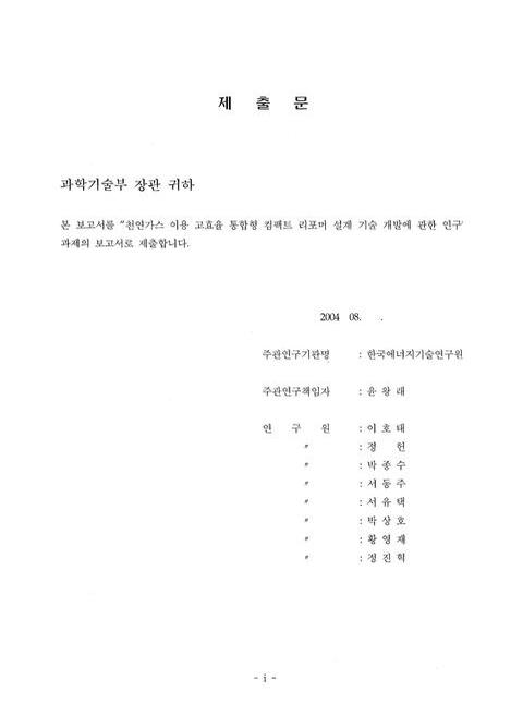
제출문=i,2,2
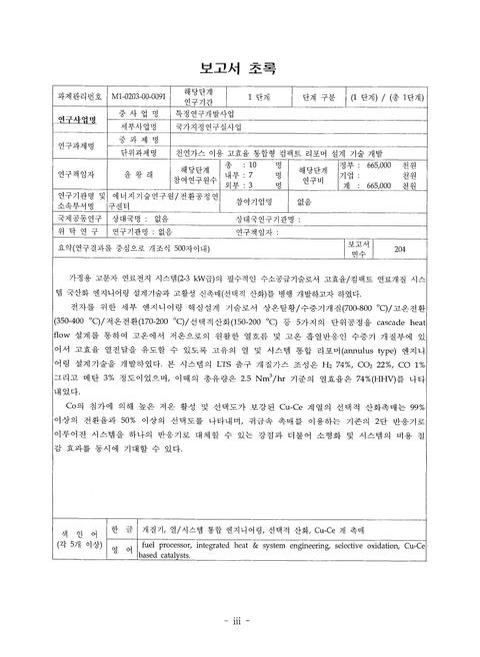
보고서 초록/윤왕래=iii,4,2
요약문=v,6,3
SUMMARY=viii,9,3
CONTENTS=xi,12,1
목차=xii,13,1
표목차=xiii,14,2
그림목차=xv,16,5
제1장 연구개발과제의 개요=1,21,1
제1절 연구개발의 필요성=1,21,2
제2절 연구개발의 범위=2,22,1
제2장 국내외 기술개발 현황=3,23,1
제1절 국외의 경우=3,23,22
제2절 국내의 경우=25,45,1
제3장 연구개발수행 내용 및 결과=26,46,1
제1절 연료개질 단위공정 분석=26,46,20
제2절 개질공정 통합엔지니어링 설계=45,65,8
제3절 운전실헙=53,73,31
제4절 선택적 CO 산화촉매 설계=84,104,75
제4장 목표달성도 및 관련분야에의 기여도=159,179,7
제5장 연구개발결과의 활용계획=166,186,13
제6장 연구개발과정에서 수집한 해외과학기술정보=179,199,2
제7장 참고문헌=181,201,3
영문목차
[title page etc.]=0,1,11
CONTENTS=xi,12,9
Chapter 1. Introduction=1,21,1
Sec 1. Necessities of the research=1,21,2
SEc 2. Approaches=2,22,1
Chapter 2. Developmental status=3,23,1
SEc 1. In Foreign Countries=3,23,22
Sec 2. In Domoestic=25,45,1
Chapter 3. Contents and Results=26,46,1
Sec 1. Unit process analysis in fuel processing=26,46,20
Sec 2. Integrated dngineering design of fuel processing system=45,65,8
Sec 3. Operation study=53,73,31
Sec 4. Design of selective CO oxidation catalyst=84,104,75
Chapter 4. Accomplishments and Contributions to the related fields=159,179,7
Chapter 5. Application plan for the results=166,186,13
Chapter 6. Oversead science and technology information throughout research & development process=179,199,2
Chapter 7. References=181,201,3
[그림 2-1-1] 1㎾급 NG 리포밍 시스템 전면 패널=21,41,1
[그림 2-1-2] 1㎾급 NG 리포밍 시스템 후면부,죄측은 반응부,우측은 증발부=21,41,1
[그림 2-1-3] 2㎾급 가정용 연료전지 시스템(Viessman Werke)=22,42,1
[그림 2-1-4] Viessmann Werke의 개질기용 버너=23,43,1
[그림 2-1-5] European fuell cell의 가정용 연료전지 공정 구성도=23,43,1
[그림 2-1-6] 1.5㎾급 가정용 연료전지 시스템=24,44,1
[그림 3-1-1] 취기제로 사용되는 주요 유황화합물의 분자 구조=27,47,1
[그림 3-1-2] Schematic activated carbon model=28,48,1
[그림 3-1-3] TDA research사의 Geode=28,48,1
[그림 3-1-4] TDA사의 상온 탈황 흡착제의 성능 평가 실험 결과=28,48,1
[그림 3-1-5] Temperature programmed desorption=29,49,1
[그림 3-1-6] Zeolite X=30,50,1
[그림 3-1-7] Desulfurizer of Tokyo gas=31,51,1
[그림 3-1-8] Na+(이미지참조)가 표면에 흡착된 caly mineral(montmorillonite)=31,51,1
[그림 3-1-9] THT adsorption breakthrough curces of selected adsorbent=33,53,1
[그림 3-1-10] Simulation용 연료개질공정 흐름도=50,70,1
[그림 3-3-1] 원통형 리포머의 열/시스템 통합화 구성=53,73,1
[그림 3-3-2] 리포머 시스템 운전 장치=54,74,1
[그림 3-3-3] Prototype-1 운전 결과,2.5 ㎾급,냉각 방식 Case 1=63,83,1
[그림 3-3-4] Prototype-1 운전 결과,2.5 ㎾급,냉각 방식 Case 2=64,84,1
[그림 3-3-5] Prototype-1 운전 결과,2.5 ㎾급,냉각 방식 Case 3=65,85,1
[그림 3-3-6] Prototype-1 운전 결과,2.5 ㎾급,냉각 방식 Case 4=66,86,1
[그림 3-3-7] Prototype-1 2.5 ㎾급 운전시 냉각 방식에 따른 메탄 전환율과 효율의 영향=67,87,1
[그림 3-3-8] Prototype-1과 Prototype-2 2.5 ㎾급 운전 시 메탄 전환율 및 연소 챔버 하단 온도 변화=69,89,1
[그림 3-3-9] Prototype-2 리포머 버너 위치에 따른 메탄 전환율의 영향 및 리포머 주요 부위 온도,2.5 ㎾ 운전,R/B 2.44=71,91,1
[그림 3-3-10] Prototype-2 원통형 통합 반응기 주요 부분별 온도 2.5 ㎾ 용량,R/D=2.44,S/C=2.5,가변형 외곽 열교환 장치,버너 위치 5.5㎝,메탄화 반응기 포함=77,97,1
[그림 3-3-11] 원통형 통합 리포머의 시동 특성 및 정상상태 특성=82,102,1
[그림 3-4-1] Schematic diagram of PrOx reactor system=88,108,1
[그림 3-4-2] Schematic diagram of temperature programmed system=93,113,1
[그림 3-4-3] Schematic of diagram experimental apparatus. The insetillustrates details of the in-situ IR reactor=94,114,1
[그림 3-4-4] Effect of transition metal oxide loaded over r-Al₂O₃ on the CO conversion(Reaction condition:1% CO,1% O₂ and 60% H₂ in N₂ balance,flow rate=100 cc/min,GHSV=60,000 h-1(이미지참조)=96,116,1
[그림 3-4-5] Effect of transition metal oxide loaded over r-Al₂O₃ on the CO conversion(Reaction condition:1% CO,1% O₂ and 60% H₂ in N₂ balance,flow rate=100 cc/min,GHSV=60,000 h-1(이미지참조)=97,117,1
[그림 3-4-6] Effect of the amount of catalysts loaded over r-Al₂O₃ on the CO conversion,(b) O₂consumption and (c) selectivity(Reaction conditions:1% CO,1% O₂ and 60% H₂ in N₂ balance,flow rate=100 cc/min,GHSV=60,000 h-1(이미지참조)=100,120,1
[그림 3-4-7] Effect of weight ratio(=Cu/(Cu+Ce))on the (a) CO conversion,(b) O₂ consumption and (c) seletivity with the reaction temperature for the selective oxidation of CO over Cu-Ce based catalysts. Reaction condirions:1% CO,1% O₂ 60% H₂,N₂ as b=101,121,1
[그림 3-4-8] Effect of various support over Cu-Ce based catalyst on the (a) CO condversion,(b) O₂ consumption,and (c) seletivity(Reaction conditions:1% CO,1% O₂ and 60% H₂ in N₂ balance,flow rate=100 cc/min,GHSV=60,000 h-1(이미지참조)=103,123,1
[그림 3-4-9] Effect of various transition metal addition to Cu-Ce/r-Al₂O₃ catalyst on the (a) CO conversion,(b) O₂ consumption,and (c) selectivity(Reaction conditions:1% CO,1% O₂ and 60% H₂ in N₂ balance,flow rate=100 cc/min,GHSV=60,000 h-1(이미=105,125,1
[그림 3-4-10] Effect of Co addition to Cu-Ce/r-Al₂O₃ catalyst on the (a) CO conversion,(b) O₂ consumption,and (c) selectivity(Reaction conditions:1% CO,1% O₂ and 60% H₂ in N₂ balance,total flow rate=100 cc/min,GHSV=60,000 h-1(이미지참조)=107,127,1
[그림 3-4-11] Change in the (a) CO conversion,(b) O₂consumption and (c) selectivity with λ for the reaction over Cu-Ce(4:16wt%)/r-Al₂O₃ catalyst(Reaction composition:1% CO,0.5~1.5% O₂,60% H₂,13% CO₂ 10% H₂O,N₂ as balance,feed rate:100 cc/min,G=109,129,1
[그림 3-4-12] Change in (a) CO conversion,(b) O₂consumption and (c) selectivity with λ for the reaction over Cu-Ce-Co(4.0:15.8:0.2 wt%) catalyst (Reaction composition:1% CO,0.5~1.25% O₂,60% H₂,N₂ as balance,feed rate=100 cc/min,GHSV=60,000 h-1(이=110,130,1
[그림 3-4-13] Change in the (a) Co conversion,(b) O₂ consumption and (c) selectivity depending on the presence of CO₂ in the reactant for the selective oxidation of CO over CuCe/A(circle) and CuCeCo0.2/A(이미지참조) (triangle down)(Solid sysmbol=with=113,133,1
[그림 3-4-14] Change in the (a) Co conversion,(b) O₂ consumption and (c) selectivity depending on the presence of H₂O in the reactant for the selective oxidation of CO over CuCe/A(circle) and CuCeCo0.2/A(이미지참조) (triangle down)(Solid sysmbol=with=116,136,1
[그림 3-4-15] Change in the (a) Co conversion,(b) O₂ consumption and (c) selectivity depending on the presence of H₂O and CO₂ in the reactant for the selective oxidation of CO over CuCe/A(circle) and CuCeCo0.2/A(이미지참조) (triangle down)(Solid sysm=119,139,1
[그림 3-4-16] Reverse water-gas shift(circle) and methanation(reverse triangle) activities of CuCe/A(solid). Reaction condition:1%CO₂+60% H₂in N₂balance,flow rate=100 cc/min.=122,142,1
[그림 3-4-17] Reverse water-gas shift(circle) and methanation(reverse triangle) activities of CuCeCo0.2/A(solid). Reaction condition:1%CO₂+60% H₂in N₂balance,flow rate=100 cc/min.=123,143,1
[그림 3-4-18] Deactiviation mode of CuCeCo0.2/A catalyst in the presence of CO₂and H₂O. Reaction condition:1% CO+1% O₂+60% H₂+(0~13)% CO₂,(0~10)% H₂O,flow rate=100 cc/min,reaction temperature=125,145,1
[그림 3-4-19] Effect of GHSV on the CO conversion and delectivity over CuCeCo0.2/A catalyst. Reaction condition:1% CO,1% O₂,60% H₂ in N₂ balance=127,147,1
[그림 3-4-20] Change in the CO conversion,O₂ consumption and selectivity with the reaction time during the selective oxidation of CO over CuCeCo0.2/A catalyst. Reaction condition:1% CO+1% O₂+60% H₂+13% CO2+10% H₂O in N₂ balance,reaction temperature=129,149,1
[그림 3-4-21] Change in the (a) Co conversion,(b) O2 consumption and (c) selectivity with the reaction temperature for the selective oxidation of CO over Pt[1 wt%]/r-A12O3(circle),Ru[1 wt%]/r-A12O3(triangle down),and Cu-Ce[4:16wt%]/r-A12O3(square).Reac=132,152,1
[그림 3-4-22] Change in the (a) Co conversion,(b) O2 consumption and (c) selectivity depending on the presence of 10% H₂O and 13% Co2 in the reaction for the selective oxidation of CO over Pt[1 wt%]/r-A12O3(circle),Ru[1 wt%/r-A12O3(Squate).Reaction con=133,153,1
[그림 3-4-23] XRD patterns for pure metal oxide=135,155,1
[그림 3-4-24] XRD patterns for various r-A1₂O₃ supported catalysts=136,156,1
[그림 3-4-25] TEM micrograph of Cu-Ce based catalysts=137,157,1
[그림 3-4-26] CO-TPR prefiles for various r-A1₂O₃ supported catalysts=141,161,1
[그림 3-4-27] H2-TPR(이미지참조) profiles or various r-A1₂O₃ supported catalysts=142,162,1
[그림 3-4-28] TPO profiles for various r-A1₂O₃ supported catalysts=143,163,1
[그림 3-4-29] CO-TPD profiles for various r-A1₂O₃ supported catalysts=145,165,1
[그림 3-4-30] H₂O-TPD(이미지참조) profiles for various r-A1₂O₃ supported catalysts=147,167,1
[그림 3-4-31] CO2-TPD(이미지참조) profiles for various r-A1₂O₃ supported catalysts=148,168,1
[그림 3-4-32] In-situ FTIR spectra(CO-TPR) of (a) Ce/A,(b) Cu/A,(c) CuCe/A and (d) CuCeCo0.2/A after 10% CO/He flowing for 10 min and purging with He for 10 min at different temperatures:(1) RT,(2) 50℃,(3) 80℃,(4) 100℃,(5) 150℃,(6) 200℃,(7) 250=153,173,1
[그림 3-4-33] In-situ FTIR spectra(CO-TPD) of (1) Ce/A,(2) Cu/A,(3) CuCe/A and (4) CuCeCo0.2/A at the temperature of(a) RT,(b) 80℃,(c) 100℃ and (d) 200℃ The samples were pretreated in 10% CO/IIe flow at 300℃ for 30 min and then followed by coolin=154,174,1
[그림 3-4-34] In-situ FTIR spectra of (a) Ce/A,(b) Cu/A,(c) CuCe/A and (d) CuCeCo0.2/A at the temperature of (1) 100℃,(2) 150℃,(3) 200℃,(4) 250℃,(5) 300℃ in PrOx condition; 2% CO+2% O2+4% H₂O+15% N2 in H2 balance=155,175,1
[그림 3-4-35] In-situ FTIR spectra(TPO) of (a) Cu/A,(b) CuCe/A and (c) CuCeCo0.2/A while flowing 30 cc/min air at 80℃ The samples were pretreated at 300℃ in 10% CO/He flow for 30 min and then cooled to 80℃ in the same gas flow=156,176,1
*표시는 필수 입력사항입니다.
| 전화번호 |
|---|
| 기사명 | 저자명 | 페이지 | 원문 | 기사목차 |
|---|
| 번호 | 발행일자 | 권호명 | 제본정보 | 자료실 | 원문 | 신청 페이지 |
|---|
도서위치안내: / 서가번호:

우편복사 목록담기를 완료하였습니다.
*표시는 필수 입력사항입니다.
저장 되었습니다.
