대표어
권호기사보기
| 기사명 | 저자명 | 페이지 | 원문 | 기사목차 |
|---|
결과 내 검색
동의어 포함
목차
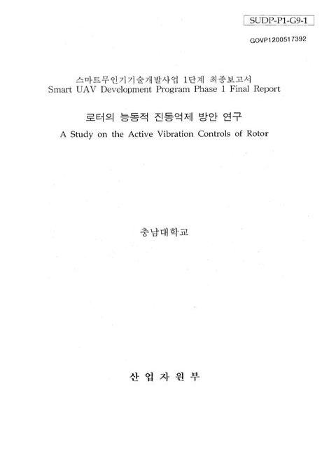
표제지=0,1,1
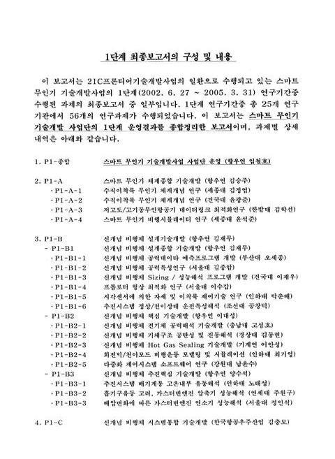
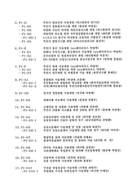
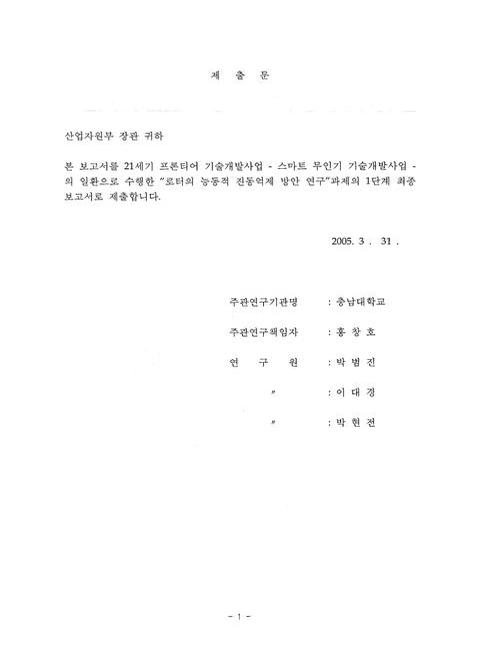
1단계 최종보고서의 구성 및 내용=0,2,2
제출문=1,4,1
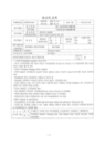
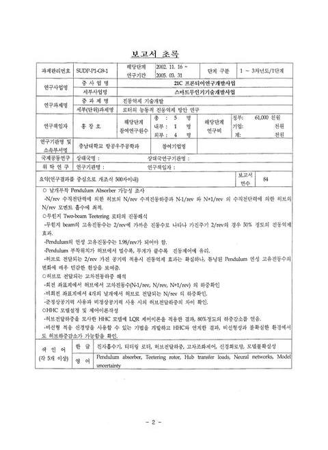
보고서 초록/홍창호=2,5,1
요약문=3,6,3
SUMMARY=6,9,2
목차=8,11,2
CONTENTS=10,13,4
제1장 연구개발과제의 개요=14,17,1
제1절 연구개발의 목적과 필요성=14,17,1
제2절 연구범위 및 내용=15,18,1
제2장 국내외 기술개발 현황=16,19,1
제1절 국내외 관련기술 현황=16,19,1
1. 국내=16,19,1
2. 국외=16,19,2
제2절 연구결과의 기술수준=17,20,1
제3장 연구개발수행 내용 및 결과=18,21,1
제1절 로터의 수동적 진동억제기법 연구=18,21,1
1. 서론=18,21,2
2. 수동적 진동흡수기=19,22,6
3. 스마트 무인기 로터 날개의 진동특성=24,27,5
4. 스마트 무인기에 적합한 진동흡수기 선택=28,31,2
5. Pendulum Absorber 부착 회전날개 연성진동해석=29,32,5
6. 무힌지 Two-beam Teetering 로터의 진동해석=33,36,5
7. 결론=38,41,1
제2절 로터의 능동적 진동억제기법 연구=39,42,1
1. 서론=39,42,2
2. 블레이드 하중과 허브 하중 계산=41,44,8
3. HHC 모델설정 및 제어이론작성=49,52,8
4. 신경회로망을 이용한 적응 고차조화제어 기법 연구=57,60,19
5. 결론=76,79,1
제4장 목표달성도 및 관련분야에의 기여도=77,80,1
제1절 목표달성도=77,80,3
제2절 관련분야에의 기여도=79,82,1
제5장 연구개발 결과의 활용계획=80,83,1
제1절 추가연구의 필요성=80,83,1
제6장 연구개발과정에서 수집한 해외과학기술정보=81,84,1
제7장 참고문헌=82,85,4
영문목차
[title page etc.]=0,1,12
CONTENTS=10,13,4
1. Outline of Research=14,17,1
1.1 Objective and Background=14,17,1
1.2 Scope=15,18,1
2. Overview of Related Technology=16,19,1
2.1 Technological Survey=16,19,1
2.1.1 Internal=16,19,1
2.1.2 International=16,19,2
2.2 Level of Present Research=17,20,1
3. Research Procedures and Results=18,21,1
3.1 Passive Method for Vibration Reduction=18,21,1
3.1.1 Introduction=18,21,2
3.1.2 Passive Vibration Absorber=19,22,6
3.1.3 Characteristics of Wing Vibration of Smart UAV=24,27,5
3.1.4 Selection of Proper Vibration Absorber for Smart UAV=28,31,2
3.1.5 Coupled Vibration Analysis of Rotor Blade with Pendulum Absorber=29,32,5
3.1.6 Vibration Analysis of Hingeless Two-beam Teetering Rotor=33,36,5
3.1.7 Conclusion=38,41,1
3.2 Active Method for Vibration Reduction=39,42,1
3.2.1 Introduction=39,42,2
3.2.2 Calculation of Blade and Hub Vibration Loads=41,44,8
3.2.3 Modeling of HHC and Derivation of Control Theory=49,52,8
3.2.4 Adaptive HHC Development Using Neural Networks=57,60,19
3.2.5 Conclusion=76,79,1
4. Evaluation of Results=77,80,1
4.1 Degree of Achievement=77,80,3
4.2 Degree of Contribution to Related Fields=79,82,1
5 Practical Usage of Research Results=80,83,1
5.1 Justification for Further Researches=80,83,1
6 Oversea's Informations of Science and Technology During Research=81,84,1
7 References=82,85,4
Figure 3.1 Flexispring absorber=20,23,1
Figure 3.2 Schematic diagram of flexispring=20,23,1
Figure 3.3 Bifilar absorber fitted to rotor head=21,24,1
Figure 3.4 Geometry and model of the bifilar=21,24,1
Figure 3.5 Schematic diagram of monofilar=22,25,1
Figure 3.6 Hughes blade mounted pendulum absorber=23,26,1
Figure 3.7 Pendulum absorber fitted to Bo105=23,26,1
Figure 3.8 Schematic diagram of Model 412 MPA with coaxial 3P and 4P cans=24,27,1
Figure 3.9 Rotor blade section=25,28,1
Figure 3.10 Position of Spar=26,29,1
Figure 3.11 Simplified spar section=26,29,1
Figure 3.12 Flap mode shapes of teetering rotor blades=27,30,1
Figure 3.13 Schematic diagram showing pendulum absorber inside blade=29,32,1
Figure 3.14 Dynamic blade-absorber model=29,32,1
Figure 3.15 Normalized without absorber=31,34,1
Figure 3.16 Normalized with absorber(absorber=2/rev)=31,34,1
Figure 3.17 Normalized with tuning pendulum's mass from 0.5㎏ to 4㎏(Red-tuning mass,Blue-baseline,m=1.0㎏)=32,35,1
Figure 3.18 Normalized with spanwise pendulum's location=33,36,1
Figure 3.19 Coordinates of teetering rotor [9]=34,37,1
Figure 3.20 Model of a teetering rotor with pendulum absorbers=34,37,1
Figure 3.21 Normalized tip deflection according to excitation period=36,39,1
Figure 3.22 Normalized tip deflection according to pendulum's length=36,39,1
Figure 3.23 Variation of amplitude according to pendulum's location=37,40,1
Figure 3.24 Variation of amplitude according to pendulum's mass=37,40,1
Figure 3.25 HHC actuator system on a three-bladed rotor=39,42,1
Figure 3.26 Diagram of active vibration control system=40,43,1
Figure 3.27 Calculation of steady response of vehicle trim and blade=41,44,1
Figure 3.28 Blade harmonic component of vertical shear force(rotational frame,quasi-steady aerodynamics)=45,48,1
Figure 3.29 Blade harmonic component of pitching moment(rotational frame,quasi-steady aerodynamics)=45,48,1
Figure 3.30 Blade harmonic component of rolling moment(rotational frame,quasi-steady aerodynamics)=46,49,1
Figure 3.31 Hub loads(fixed frame,quasi-steady aerodynamics)=46,49,1
Figure 3.32 Blade harmonic component of vertical shear force(rotational frame,unsteady aerodynamics)=47,50,1
Figure 3.33 Blade harmonic component of pitching moment(rotational frame,unsteady aerodynamics)=47,50,1
Figure 3.34 Blade harmonic component of rolling moment(rotational frame,unsteady aerodynamics)=48,51,1
Figure 3.35 Hub loads(fixed frame,unsteady aerodynamics)=48,51,1
Figure 3.36 Position of actuators for periodic input to swash plate=51,54,1
Figure 3.37 Flow chart of algorithm for active vibration control=54,57,1
Figure 3.38 Load factors for accurate input model=56,59,1
Figure 3.39 Load factors for input with measurement noise=56,59,1
Figure 3.40 Load factors for input with inaccurate transfer matrix=56,59,1
Figure 3.41 Load factors for input with measurement noise and inaccurate transfer matrix=56,59,1
Figure 3.42 Diagram of neural networks=60,63,1
Figure 3.43 Diagram of vibration suppression using neural networks=63,66,1
Figure 3.44 Performance of vibration suppression(accurate transfer matrix)=67,70,1
Figure 3.45 Control inputs to scheme using optimal output regulator(accurate transfer matrix)=67,70,1
Figure 3.46 Control inputs to neural networks(accurate transfer matrix)=68,71,1
Figure 3.47 Performance of vibration suppression(inaccurate transfer matrix)=68,71,1
Figure 3.48 Control inputs to scheme using optimum output regulator(inaccurate transfer matrix)=69,72,1
Figure 3.49 Control inputs to neural networks(inaccurate transfer matrix)=69,72,1
Figure 3.50 Results of weight learning in neural networks=70,73,1
Figure 3.51 Relationship between 1st and 2nd flap periods=71,74,1
Figure 3.52 Hub shear forces according to 2nd flap frequency=72,75,1
Figure 3.53 Hub moments according to 2nd flap frequency=72,75,1
Figure 3.54 Components of output harmonics to accurate transfer matrix(LQR)=73,76,1
Figure 3.55 HHC inpus to accurate transfer matrix(LQR)=73,76,1
Figure 3.56 Components of output harmonics to inaccurate transfer matrix(LQR)=74,77,1
Figure 3.57 HHC inpus to inaccurate transfer matrix(LQR)=74,77,1
Figure 3.58 Components of output harmonics to inaccurate transfer matrix(neural networks)=75,78,1
Figure 3.59 HHC inpus to inaccurate transfer matrix(neural networks)=75,78,1
*표시는 필수 입력사항입니다.
| 전화번호 |
|---|
| 기사명 | 저자명 | 페이지 | 원문 | 기사목차 |
|---|
| 번호 | 발행일자 | 권호명 | 제본정보 | 자료실 | 원문 | 신청 페이지 |
|---|
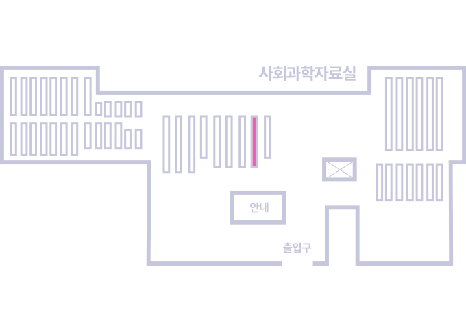
도서위치안내: / 서가번호:
우편복사 목록담기를 완료하였습니다.
*표시는 필수 입력사항입니다.
저장 되었습니다.