
 대표어
대표어


권호기사보기
| 기사명 | 저자명 | 페이지 | 원문 | 기사목차 |
|---|
결과 내 검색
동의어 포함
표제지
목차
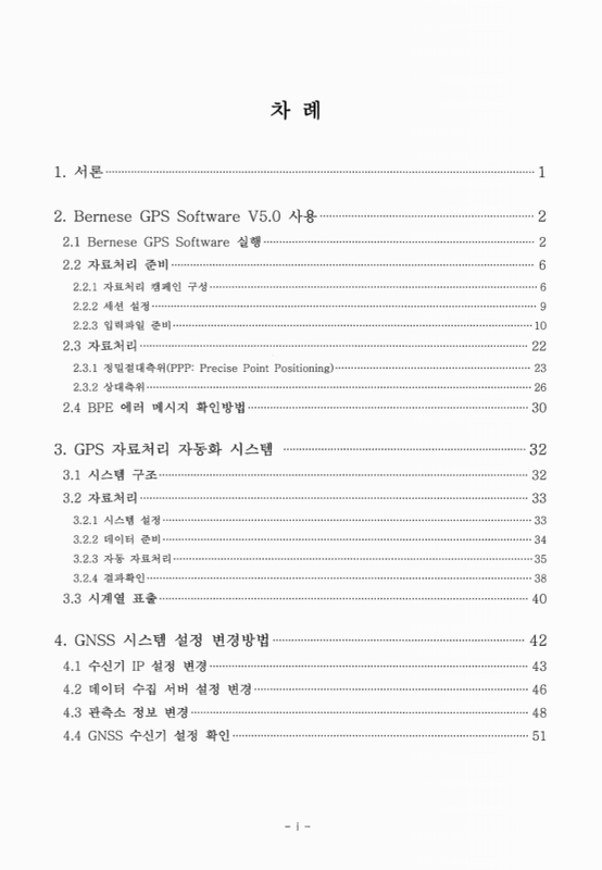
1. 서론 7
2. Bernese GPS Software V5.0 사용 8
2.1. Bernese GPS Software 실행 8
2.2. 자료처리 준비 12
2.2.1. 자료처리 캠페인 구성 12
2.2.2. 세션 설정 15
2.2.3. 입력파일 준비 16
2.3. 자료처리 28
2.3.1. 정밀절대측위 (PPP: Precise Point Positioning) 29
2.3.2. 상대측위 32
2.4. BPE 에러 메시지 확인방법 36
3. GPS 자료처리 자동화 시스템 38
3.1. 시스템 구조 38
3.2. 자료처리 39
3.2.1. 시스템 설정 39
3.2.2. 데이터 준비 40
3.2.3. 자동 자료처리 41
3.2.4. 결과확인 44
3.3. 시계열 표출 46
4. GNSS 시스템 설정 변경방법 48
4.1. 수신기 IP 설정 변경 49
4.2. 데이터 수집 서버 설정 변경 52
4.3. 관측소 정보 변경 54
4.4. GNSS 수신기 설정 확인 57
참고문헌 58
부록 59
부록 A-1. Control script of the auto GPS data processing system : 'AutoRun.sh' 59
부록 A-2. Plot time series graph of daily solutions : 'Timeseries_daily.m' 62
Figure 2.1. Setup Xming and save configuration file. 9
Figure 2.2. Setup options of PuTTY. 10
Figure 2.3. Login data processing server. 10
Figure 2.4. Run Bernese GPS Software. 11
Figure 2.5. Menu of Bernese GPS Software V5.0. 11
Figure 2.6. Edit list of campaigns step1. 12
Figure 2.7. Edit list of campaigns step2. 13
Figure 2.8. Select active campaign 13
Figure 2.9. Create new campaign directories 14
Figure 2.10. Set session and compute date. 15
Figure 2.11. Edit session table. 16
Figure 2.12. Download BULLET_A.ERP file from CODE server. 17
Figure 2.13. Download three(ION, 2 DCBs) files from CODE server. 18
Figure 2.14. Download three(CLK, SP3, ERP) files from IGS server. 18
Figure 2.15. Statute of campaign directory after 2.2.3.1 chapter. 19
Figure 2.16. Ocean tide loading webpage and options to get the tide values at each stations 21
Figure 2.17. Get station information from RINEX files. 22
Figure 2.18. Edit station information file. 23
Figure 2.19. Edit and check coordinate file. 24
Figure 2.20. Edit and check velocity file. 25
Figure 2.21. Statute of campaign directory after 2.2.3.3 chapter. 26
Figure 2.22. Download general files from CODE server. 27
Figure 2.23. PPP processing step 1. 29
Figure 2.24. PPP processing step 2. 29
Figure 2.25. PPP processing step 3. 30
Figure 2.26. PPP processing step 4. 30
Figure 2.27. PPP processing step 5. 31
Figure 2.28. PPP processing step 6. 31
Figure 2.29. STA directory structure after PPP processing. 32
Figure 2.30. RNX2SNX processing step 1. 33
Figure 2.31. RNX2SNX processing step 2. 33
Figure 2.32. RNX2SNX processing step 3. 34
Figure 2.33. RNX2SNX processing step 4. 34
Figure 2.34. Ambiguity fixed final result file. 35
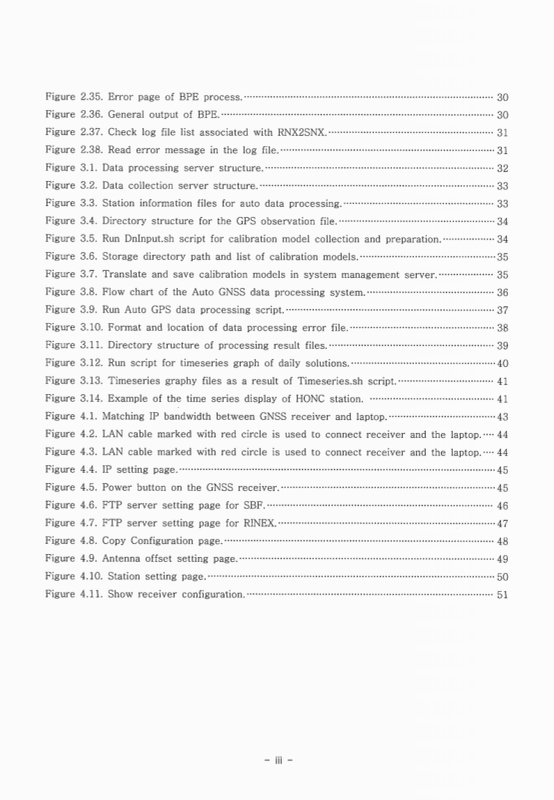
Figure 2.35. Error page of BPE process. 36
Figure 2.36. General output of BPE. 36
Figure 2.37. Check log file list associated with RNX2SNX. 37
Figure 2.38. Read error message in the log file. 37
Figure 3.1. Data processing server structure. 38
Figure 3.2. Data collection server structure. 39
Figure 3.3. Station information files for auto data processing. 39
Figure 3.4. Directory structure for the GPS observation file. 40
Figure 3.5. Run DnInput.sh script for calibration model collection and preparation. 40
Figure 3.6. Storage directory path and list of calibration models. 41
Figure 3.7. Translate and save calibration models in system management server. 41
Figure 3.8. Flow chart of the Auto GNSS data processing system. 42
Figure 3.9. Run Auto GPS data processing script. 43
Figure 3.10. Format and location of data processing error file. 44
Figure 3.11. Directory structure of processing result files. 45
Figure 3.12. Run script for timeseries graph of daily solutions. 46
Figure 3.13. Timeseries graphy files as a result of Timeseries.sh script. 47
Figure 3.14. Example of the time series display of HONC station. 47
Figure 4.1. Matching IP bandwidth between GNSS receiver and laptop. 49
Figure 4.2. LAN cable marked with red circle is used to connect receiver and the laptop. 50
Figure 4.3. LAN cable marked with red circle is used to connect receiver and the laptop. 50
Figure 4.4. IP setting page. 51
Figure 4.5. Power button on the GNSS receiver. 51
Figure 4.6. FTP server setting page for SBF. 52
Figure 4.7. FTP server setting page for RINEX. 53
Figure 4.8. Copy Configuration page. 54
Figure 4.9. Antenna offset setting page. 55
Figure 4.10. Station setting page. 56
Figure 4.11. Show receiver configuration. 57
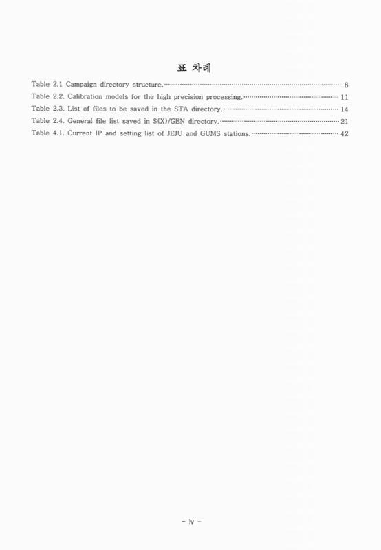
Box 2.1. EXAMPLE.PLD file format. 21
Box 2.2. IGS_00_R.CRD file format. 23
Box 2.3. IGS_00_R. VEL file format. 24
Box 2.4. IGS_00.FIX file format. 25
Box 2.5. PCF file format. 28
Box 2.6. Coordinates result of Precise Point Positioning 32
Box 2.7. Coordinates result of RNX2SNX 35
| 등록번호 | 청구기호 | 권별정보 | 자료실 | 이용여부 |
|---|---|---|---|---|
| 0001965647 | 551.6354 -14-8 | 서울관 서고(열람신청 후 1층 대출대) | 이용가능 | |
| 0001965648 | 551.6354 -14-8 | 서울관 서고(열람신청 후 1층 대출대) | 이용가능 |
*표시는 필수 입력사항입니다.
| 전화번호 |
|---|
| 기사명 | 저자명 | 페이지 | 원문 | 기사목차 |
|---|
| 번호 | 발행일자 | 권호명 | 제본정보 | 자료실 | 원문 | 신청 페이지 |
|---|
도서위치안내: / 서가번호:

우편복사 목록담기를 완료하였습니다.
*표시는 필수 입력사항입니다.
저장 되었습니다.
