
 대표어
대표어


권호기사보기
| 기사명 | 저자명 | 페이지 | 원문 | 기사목차 |
|---|
결과 내 검색
동의어 포함
Title Page
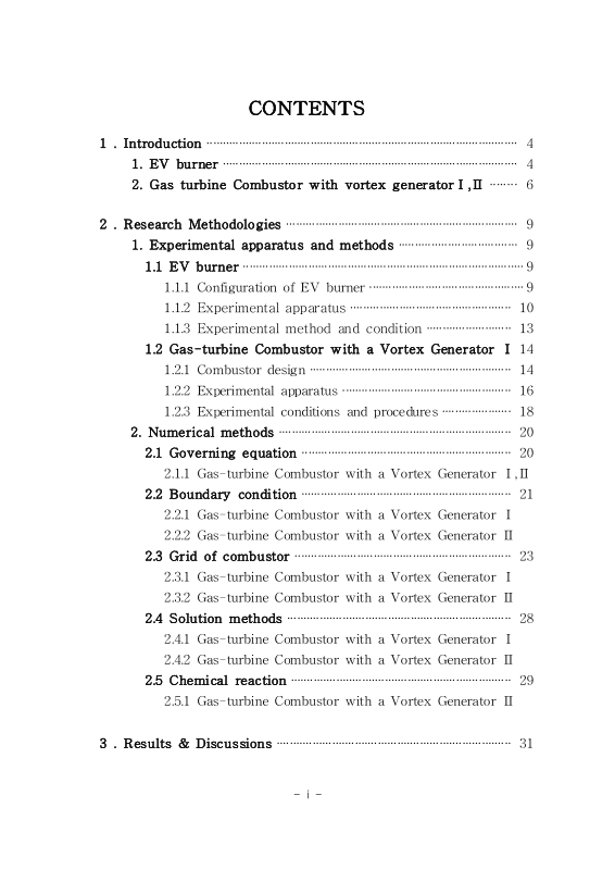
Contents
NOMENCLATURE 9
ABSTRACT 13
1. Introduction 16
1. EV burner 16
2. Gas turbine Combustor with vortex generator I, II 18
2. Research Methodologies 21
1. Experimental apparatus and methods 21
1.1. EV burner 21
1.2. Gas-turbine Combustor with a Vortex Generator I 26
2. Numerical methods 32
2.1. Governing equations 32
2.2. Boundary condition 33
2.3. Grid of combustor 35
2.4. Solution methods 40
2.5. Chemical reaction 41
3. Results & Discussions 43
1. Experimental results of EV burner 43
2. Experimental, Numerical study results of gas turbine combustor with a vortex generator I 59
3. Numerical combustion study results of gas turbine combustor with a vortex generator II 71
4. Conclusion 82
REFERENCES 85
국문초록 92
Fig. 1. EV burner geometry 21
Fig. 2. Experimental apparatus with a premixed flame combustor 23
Fig. 3. Locations of measured temperature 24
Fig. 4. Pictures and drawings of the combustor and combustor assembly 27
Fig. 5. Experimental apparatus for a lean-premixed flame test combustor 29
Fig. 6. Geometry and unstructured grids of combustor with a vortex generator I 36
Fig. 7. Geometry and unstructured grids of combustor with a vortex generator II 39
Fig. 8. Effect of inlet air temperature on NOx emissions(이미지참조) 44
Fig. 9. Effect of inlet air temperature on CO emissions 45
Fig. 10. Effect of Various Load on NOx emissions (Inlet temperature 370℃)(이미지참조) 47
Fig. 11. Effect of Various Load on CO emissions (Inlet temperature 370℃) 48
Fig. 12. Temperature characteristics at the front wall of the burner 50
Fig. 13. Temperature characteristics at the side wall of the burner 52
Fig. 14. Temperature characteristics of combustor liner 54
Fig. 15. Characteristics of pressure loss across the burner 56
Fig. 16. Characteristics of Flame extinction point 58
Fig. 17. Recirculation flow patterns without and with the vortex generator (streamline of the recirculation flow within the combustor liner at nozzle exit velocity, 20m/s) 59
Fig. 18. Shear stress calculation results with and without vortex generator (at combustor nozzle exit velocity, 20m/s) 60
Fig. 19. NOx emission characteristics relative to the changes of combustor exit velocity and equivalence ratio(이미지참조) 63
Fig. 20. CO emission characteristics relative to the changes of combustor exit velocity and equivalence ratio 65
Fig. 21. OH radical's chemiluminescence images at various operating conditions 68
Fig. 22. Location of maximum intensity of OH radical's chemiluminescence 70
Fig. 23. Vortex core regions calculated in case 0(upper plot) and case 1(lower plot) 72
Fig. 24. Cross-sectional view of burner and liner including burner-inside line 73
Fig. 25. Static-pressure profiles along the burner-inside line in case 0 and case 1(pressure value is expressed in gauge pressure) 74
Fig. 26. Radial profiles of NOx concentration at 3 different sections in cases 0 and 1(이미지참조) 78
Fig. 27. Temperature fields on xz plane in the liner 79
Fig. 28. Axial velocity fields on xz plane in a burner 81
*표시는 필수 입력사항입니다.
| 전화번호 |
|---|
| 기사명 | 저자명 | 페이지 | 원문 | 기사목차 |
|---|
| 번호 | 발행일자 | 권호명 | 제본정보 | 자료실 | 원문 | 신청 페이지 |
|---|
도서위치안내: / 서가번호:

우편복사 목록담기를 완료하였습니다.
*표시는 필수 입력사항입니다.
저장 되었습니다.
